6.3. Parameter customization

As of MCAF R4, parameter customization is available through the Customize page of motorBench® Development Suite, which provides access to various parameters that affect code generation.

This section provides additional guidance for setting these parameters.

Please note: MCAF has been designed so that the default values for customizable parameters are applicable to most motors. In the event that it is unclear what to do, the best course of action is to use the default value of each parameter.

6.3.1. Summary

The following table describes these parameters briefly. Links to detailed guidance are included.

Table 6.1 Customizable parameters
Section Parameter Description
Estimators Primary estimator Selects which estimator is used for commutation and velocity feedback.
Estimators Active estimators Selects which estimators are active, in addition to the primary estimator used for commutation
Operating parameters Minimum velocity Determines minimum operating velocity
Operating parameters Coastdown: Velocity threshold Determines velocity threshold used to estimate when a motor stops
Operating parameters Coastdown: Time Determines time to wait until a motor stops
Operating parameters Slew rate: max acceleration Determines maximum velocity slew rate in motoring quadrants
Operating parameters Slew rate: max deceleration Determines maximum velocity slew rate in generating quadrants
Operating parameters Max velocity Determines maximum velocity command, as a ratio of nominal motor velocity
Operating parameters Full-scale velocity Determines full-scale velocity, as a ratio of nominal motor velocity
Operating parameters Saliency: Saliency threshold Determines saliency ratio below which the motor’s saliency is neglected
Flux control Flux control method Selects flux control method (or “None” if disabled)
Flux control Current limit: Boundary type Selects method used for defining the commanded Idq boundary
Flux control Current limit: Idmax Determines the maximum negative d-axis current
Flux control Current limit: Iqmax Determines the maximum q-axis current
Flux control Flux weakening: Voltage limit Determines the voltage amplitude limit used in flux weakening (FW)
Flux control MTPA: Idmax-MTPA Displays the maximum d-axis current allocated to MTPA, as a function of (Ld − Lq) and Imax (Indication only)
Flux control MTPA: gain-MTPA Displays the maximum increase in torque due to MTPA (Indication only)
Dead-time compensation Dead-time compensation method Selects dead-time compensation method (or “None” if disabled)
Dead-time compensation Current linearity range Determines linear range of currents used for deadtime compensation; larger currents are treated as ±1
Dead-time compensation Forward gain Determines gain for dead-time compensation in the forward path
Dead-time compensation Feedback gain Determines gain for dead-time compensation in the feedback path
Fault detection Undervoltage margin Determines undervoltage threshold margin
Fault detection Overvoltage margin Determines overvoltage threshold margin
Startup Startup current Determines current used during startup
Startup Rampup time Determines current rampup time during startup
Startup Align time Determines time to remain in the align state during startup
Startup Min accel time Determines minimum acceleration time during startup
Startup Acceleration \(\alpha_1\) Determines fast acceleration rate
Startup Acceleration \(\alpha_0\) Determines slow acceleration rate
Startup Hold time Determines time to remain in the hold state during startup
Startup Speed threshold \(\omega_0\) Determines speed threshold for switching to fast acceleration
Startup Angle converge rate Determines rate of angle convergence during closed-loop transition of classic startup
Startup Startup algorithm Selects startup method
Startup Active damping: max amplitude Determines maximum amplitude of active damping current
Startup Active damping: max gain Determines maximum gain of active damping
Startup Active damping: speed threshold Determines the minimum velocity to enable active damping
Overmodulation D-axis limit Determines the maximum d-axis voltage
Overmodulation Q-axis limit Determines the maximum q-axis voltage
AN1292 PLL Time constant Specifies the velocity estimation time constant
AN1292 PLL Loop filter bandwidth Specifies the loop filter bandwidth
AN1292 PLL Filter threshold Determines maximum velocity for slow filtering in the PLL
Quadrature encoder Lines Specifies the number of lines of the encoder
Quadrature encoder Index pulse present Specifies whether an index pulse is present
Quadrature encoder Tracking loop time constant Determines bandwidth of tracking loop
Quadrature encoder Synchronization method Selects method of synchronizing encoder with back-emf
Quadrature encoder Align angle shift Determines angle shift between rampup and align states of startup
Quadrature encoder Align initial angle Determines initial angle used in rampup state of startup
Quadrature encoder Align-and-sweep rate Determines rotation rate during align state of startup, when using align-and-sweep method
Quadrature encoder Align-and-sweep setup angle Determines setup angle of align-and-sweep method, to allow transients to settle prior to measurements
Quadrature encoder Pullout slip threshold Determines rotor slip threshold used for detecting a pullout condition
Motion Control API Filter time constant Is Determines the time constant used for calculating low pass filtered value of amplitude of current in the motor (Is)
Motion Control API Filter time constant Iq Determines the time constant used for calculating low pass filtered value of the measured q-axis current in the motor (Iq)
Board Service UI service period Determines the rate at which the board service ISR tasks get executed.
Board Service Button debounce time Determines the length of time required to register a logical high signal as a button press.
Board Service Long button press time Determines the amount of time before a button press is detected as a long button press.

6.3.2. Detailed information

6.3.2.1. Estimators

6.3.2.1.1. Primary estimator

One position and velocity estimator must be chosen for use in commutation and velocity feedback.

Available estimators in MCAF R5:

New in version R5.

(Previously this choice was made on the Configure page in motorBench® Development Suite.)

6.3.2.1.2. Active estimators

In addition to the primary estimator, additional estimators may be selected. (Only the primary estimator is used for commutation and velocity feedback.)

Usage of more than one estimator — particularly the quadrature encoder, which has higher angle and velocity accuracy — is recommended for troubleshooting or validation purposes. Please note that this will increase CPU and memory requirements.

New in version R4.

6.3.2.2. Operating parameters

6.3.2.2.1. Minimum velocity

Minimum velocity \(\omega_1\) was moved in MCAF R5 to the Customize page from the Configure page. It is used in MCAF in three ways:

  • Determines the lower limit of the adjustable velocity range
  • Determines the transition speed during motor startup, from open-loop commutation to closed-loop commutation
  • In autotuning, determines dynamics of the sensorless estimator model; stability and performance of sensorless estimators are poorer at lower velocities, so lowering the minimum velocity will generally result in a lower-bandwidth velocity control loop to ensure stability.

New in version R5.

6.3.2.2.2. Coastdown parameters

There are two interrelated coastdown parameters used to estimate the time required to bring the motor to a stop, before it can be safely restarted:

  • velocity threshold
  • time

The resulting coastdown time is used in the STOPPING state before proceeding to the STOPPED state.

New in version R5.

6.3.2.2.3. Slew rate (max acceleration/deceleration)

Maximum acceleration (in motoring quadrants) and deceleration (in generating quadrants) can be adjusted. Increasing the slew rates will increase the motor current required during acceleration or deceleration.

Determining maximum deceleration during regeneration must be done with some care: the motor drive converts mechanical energy into electrical energy, which must go somewhere, such as a battery or a dynamic brake resistor. Without a viable outlet for that energy, the DC link voltage will rise until the motor controller detects this and shuts down, or until one of the capacitors or transistors fails and dissipates this energy destructively.

New in version R5.

6.3.2.2.4. Max velocity

Increase or decrease the maximum allowed velocity command, as a ratio of nominal motor velocity. The default value is sufficient in most cases. Increasing may be appropriate for motors with a wide flux weakening range above the nominal velocity.

New in version R6.

6.3.2.2.5. Full-scale velocity

The full-scale velocity controls the numerical representation of motor velocity. Increase to allow more design margin against overflow.

New in version R6.

6.3.2.2.6. Saliency threshold

Saliency ratio \(\xi = L_q/L_d\) helps determine whether the full-saliency motor model is used. This is a more complicated motor model, used in certain algorithms such as the ATPLL estimator, MTPA, and flux weakening. The full-saliency motor model takes both inductances into account, but requires slightly more computation. Since most permanent-magnet motors are non-salient, \(\xi \approx 1\) and the saliency can be neglected, saving CPU cycles.

This threshold sets the minimum saliency to use the full-saliency motor model. Increasing the threshold can be used to neglect saliency if the extra computation is not desirable.

New in version R6.

6.3.2.3. Flux control

See the section on flux control for more information.

6.3.2.3.1. Flux control method

Selects which flux control method is used, from among the following:

  • “None” — d-axis reference current will be set to zero
  • “Equation-based” — determines d-axis reference current from the flux weakening and MTPA algorithms

New in version R6.

6.3.2.3.2. Current limit: Boundary type

Rectangular type sets d-axis and q-axis current limits independently. Quadratic type sets the q-axis limit based on a quadratic approximation of a circular function.

See also Calculation of q-axis current limit for more information.

New in version R6.

6.3.2.3.3. Current limit: Idmax

The d-axis current is normalized to maximum current Imax, where Imax = minimum of motor and drive continuous current ratings. It is recommended to set the current limit below the demagnetizing current of the motor.

New in version R6.

6.3.2.3.4. Current limit: Iqmax

The q-axis current limit is allocated as a fraction of current limit Imax, where Imax = minimum of motor and drive continuous current ratings. This is applicable only when rectangular boundary type is enabled.

See also Calculation of q-axis current limit for more information.

New in version R6.

6.3.2.3.5. Flux weakening: voltage limit

The voltage amplitude limit used in flux weakening (FW) is normalized to DC link voltage. D-axis current is computed so that the steady-state voltage requirements do not exceed this circular limit. Ideally a limit is chosen so that the motor enters FW operation just before entering overmodulation. Higher limits may prevent the motor from entering FW region. Lower limits guarantee FW operation, at the cost of extra power dissipation.

New in version R6.

6.3.2.3.6. MTPA display calculations

MTPA does not have any user-configurable parameters, but does include two display values for indication only:

  • \(I_{\textnormal{dmax\_mtpa}}\) — displays the maximum d-axis current reference that can occur from MTPA
  • \(G_{\textnormal{mtpa}}\) — displays the maximum torque gain that can occur from the use of MTPA, relative to the maximum torque with MTPA disabled (\(I_d = 0\)).

Both are generally very small, except for motors that have significant rotor saliency and high flux utilization. The saliency flux utilization coefficient \(\alpha_{\textrm{mtpa}} = (L_q-L_d)I_{\max}/\psi_m\) is a metric of rotor saliency and flux utilization, and represents how much change in air-gap flux can occur, relative to the permanent magnet flux.

The maximum d-axis current and maximum torque gain are approximately proportional to \(\alpha_{\textrm{mtpa}}{}^2\), so doubling the overall current capability \(I_{\max}\) roughly quadruples both the d-axis current requested by MPTA and the contribution of MTPA towards torque.

New in version R6.

6.3.2.4. Dead-time compensation

See the section on dead-time compensation for more information.

6.3.2.4.1. Dead-time compensation method

Selects which dead-time compensation method is used, from among the following:

New in version R6.

6.3.2.4.2. Current linearity range

Determines the maximum amplitude \(I_\delta\) for which a linear range of current is used in calculating unit disturbance signals \(\hat{s}_{abc}\) — see per-phase dead-time compensation and the current linearity range.

New in version R6.

6.3.2.4.3. Forward gain

Determines the dead-time compensation gain used in the forward path to mitigate the effects of dead time distortion at high electrical frequencies. Unless this type of dead-time compensation is tested carefully with a specific motor, the default value of zero is recommended. See forward-path gain for more information.

New in version R6.

6.3.2.4.4. Feedback gain

Determines the dead-time compensation gain used in the feedback path to mitigate the effects of dead time distortion on sensorless estimators at low speeds. Increasing this gain will generally improve sensorless estimator performance at low speeds, but excessive gain may cause the current command to jump to its positive limit. See feedback-path gain for more information.

New in version R6.

6.3.2.5. Fault detection

6.3.2.5.1. Undervoltage margin

Determines the point at which the motor controller shuts down due to insufficient available voltage below its minimum operating voltage.

New in version R5.

6.3.2.5.2. Overvoltage margin

Determines the point at which the motor controller shuts down due to excessive voltage above its maximum operating voltage.

New in version R5.

6.3.2.6. Startup

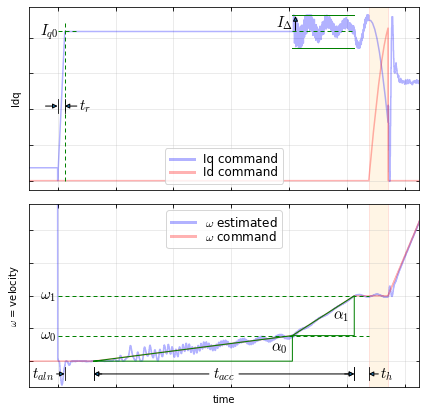
The startup sequence has numerous parameters that can be modified. These are shown in Figure 6.1.

../_images/startup-sequence.png

Figure 6.1 Graph of current and electrical frequency in startup sequence. (The Weathervane startup algorithm is shown.)

6.3.2.6.1. Startup current

Startup current amplitude \(I_{q0}\) represents a tradeoff between making startup robust (higher is better) and reducing power dissipation in the motor (lower is better). There’s not much value in reducing it below 0.5, which specifies half of maximum continuous current.

New in version R4.

6.3.2.6.2. Rampup time

Current rampup time \(t_r\) affects only the initial state of startup, in which current increases from zero to its maximum amplitude. The current rampup time should be slow compared to \(L/R\), so that it represents a smooth transition, but fast compared to the overall startup time.

New in version R4.

6.3.2.6.3. Align time

Some motors, especially those with large inertia and cogging torque, may start more reliably with align time \(t_{aln} > 0\). The default value of zero is sufficient in most cases.

New in version R5.

6.3.2.6.4. Min accel time

Increase the minimum acceleration time \(t_{acc}\) if a slower, less-aggressive startup is desired.

New in version R4.

6.3.2.6.5. Acceleration \(\alpha_1\)

Increase or decrease the acceleration rate \(\alpha_1\) to control the faster second phase of acceleration. Slower acceleration is generally less prone to cycle slips, but takes longer.

New in version R4.

6.3.2.6.6. Acceleration \(\alpha_0\)

Increase or decrease the acceleration rate \(\alpha_0\) to control the slower first phase of acceleration. (Note: this is normalized to \(\alpha_1\).) Slower acceleration is generally less prone to cycle slips, but takes longer.

New in version R4.

6.3.2.6.7. Hold time

The hold time \(t_h\) controls how long the startup sequence remains in the HOLD state where electrical frequency and current are both held constant before transitioning to closed-loop commutation.

A value of zero is fine in most cases.

New in version R5.

6.3.2.6.8. Speed threshold \(\omega_0\)

Decreasing the velocity threshold \(\omega_0\) will switch to the faster second phase of acceleration sooner.

(Note that the threshold \(\omega_1\) is determined by the minimum velocity setting under Operating parameters.)

New in version R4.

6.3.2.6.9. Angle converge rate

The angle converge rate controls how fast the transition from open-loop to closed-loop commutation with the Classic startup method.

Some motors may require a lower value to ensure a smooth transition to closed-loop commutation, typically in the range of 0.1°/ms – 1.0°/ms.

New in version R5.

6.3.2.6.10. Startup algorithm

Classic is the algorithm provided in MCAF R1-R3. Weathervane transitions to closed-loop more quickly than the Classic algorithm.

See choice of startup method.

New in version R4.

6.3.2.6.11. Active damping: max amplitude

Controls the amplitude of active damping \(I_\Delta\). Reduce this value if startup is noisy or unstable. Set to zero to eliminate active damping completely.

New in version R4.

6.3.2.6.12. Active damping: max gain

Controls the feedback gain of active damping. Reduce this value if startup is noisy or unstable.

New in version R4.

6.3.2.6.13. Active damping: speed threshold

Determines the minimum velocity to enable active damping. Make sure to choose a velocity where the estimator is stable enough to be useful for active damping.

New in version R4.

6.3.2.7. Overmodulation

See the section on overmodulation for more information.

6.3.2.7.1. D-axis limit

Determines the maximum d-axis voltage. Leaving this at 1.0 is recommended.

New in version R4.

6.3.2.7.2. Q-axis limit

Determines the maximum q-axis voltage. A value between 1.05 and 1.25 is recommended. Larger values will allow higher output voltage amplitude, at the cost of higher distortion in output voltage and current.

The section on overmodulation behavior in the synchronous frame has more information on this subject.

New in version R4.

6.3.2.8. AN1292 PLL

See the section on AN1292 Phase-locked Loop (PLL) for more information.

6.3.2.8.1. Time constant

Determines the time constant \(\tau\) used for velocity estimation. This does not affect estimator stability, but it does impact the velocity control loop performance. Lower values of time constant let more noise through, but allow higher-bandwidth velocity loops. Higher values of time constant filter out more noise, but reduce the achievable velocity loop bandwidth.

New in version R5.

6.3.2.8.2. Loop filter bandwidth

Determines the loop filter bandwidth \(\omega_1\) used for angle estimation in the PLL. (Note: this is a different value than the minimum operating velocity, also called \(\omega_1\))

Leaving this value at its default is recommended.

New in version R5.

6.3.2.8.3. Filter threshold

Determines the maximum velocity for slow filtering in the PLL estimator. Leaving this value at its default is recommended.

New in version R6.

6.3.2.9. Quadrature encoder

See the section on quadrature encoder support for more information.

6.3.2.9.1. Lines

This should match the number of lines, or cycles per revolution (CPR), listed in the datasheet of the motor or encoder. The number of counts per revolution is 4× the number of lines.

New in version R4.

6.3.2.9.2. Index pulse present

Select this option if an index pulse signal is present.

New in version R4.

6.3.2.9.3. Tracking loop time constant

Values in the 1 ms - 10 ms range are recommended. Smaller values will increase estimator bandwidth but allow more encoder quantization noise to appear in the velocity estimate. Larger values will decrease estimator bandwidth, along with the achievable velocity loop bandwidth, but will decrease the effect of encoder quantization noise.

Note: With MCAF R4, out-of-range errors in code generation will occur for certain combinations of motors with low speed ratings, and choices of tracking loop time constant. This is expected when \(\omega_{m1} \tau < \theta_L\) where \(\theta_L \approx 0.4\ \text{rad}\), where \(\omega_{m1}\) is the rated motor velocity in rad/s, and \(\tau\) is the tracking loop time constant. A viable workaround in most cases is to increase the tracking loop time constant, though this would reduce the velocity loop bandwidth.

For example, a motor with rated velocity of 2000 RPM ≈ 209 rad/s is likely to have out-of-range errors if the tracking loop time constant is less than approximately \(0.4 / 209 = 0.0019\) s or 1.9 ms.

New in version R4.

6.3.2.9.4. Synchronization method

  • Align — best general-purpose synchronization method, fastest, sensitive to large cogging torque
  • Pullout — most immune to cogging torque, sensitive to high inertia
  • Align-and-sweep — slow, best accuracy

New in version R4.

6.3.2.9.5. Align time

This determines the align time used for back-emf synchronization. Systems with larger inertia may need longer times. Shorter times (less than 0.5 s) may be adequate for very low inertia systems.

New in version R4.

6.3.2.9.6. Align angle shift

Increase this angle for systems with high cogging torque. Values of 30° - 60° are recommended.

New in version R4.

6.3.2.9.7. Align initial angle

Controls the initial electrical angle used during the rampup state of startup. Some angles may be slightly more robust, but this must be determined empirically for a particular motor.

New in version R4.

6.3.2.9.8. Align-and-sweep rate

4 counts per ISR is the fastest, and is adequate for most motors with low cogging torque. Decrease this value for motors with high cogging torque.

New in version R4.

6.3.2.9.9. Align-and-sweep setup angle

This controls the setup angle prior to making commutation offset measurements. Smaller values may not leave enough time for transients to settle. Larger values will add more time for transients to settle. Increasing it for high-inertia systems may improve accuracy.

New in version R4.

6.3.2.9.10. Pullout slip threshold

This parameter controls the slip at which pullout offset is measured for determining commutation offset. Slip here is defined as the rate of change of difference in the angle of the stationary frame voltage vector \(V_{\alpha\beta}\) and the raw electrical position from the encoder. Good choices for this parameter depend on the motor’s mechanical properties, namely inertia \(J\), viscous damping \(B\), and friction torque \(T_{fr}\). The slip threshold may need to be increased for motors with low inertia, or decreased for motors with higher inertia. The recommended range for slip threshold is approximately 0.059 to 0.47 rad/s. (0.5× to 4× the default value)

New in version R4.

6.3.2.10. Motion Control API

See the section on Motion Control API for more information.

6.3.2.10.1. Filter time constant Is

Values of the order of 0.1ms – 10ms are recommended. Higher time constant values reduce noise in the Is signal that is made available through MCAPI at the cost of adding some phase delay compared to the sampled value of Is in MCAF.

New in version R6.

6.3.2.10.2. Filter time constant Iq

Values of the order of 0.1ms – 10ms are recommended. Higher time constant values reduce noise in the Iq signal that is made available through MCAPI at the cost of adding some phase delay compared to the sampled value of Iq in MCAF.

New in version R6.

6.3.2.11. Board service

6.3.2.11.1. UI service period

Determines the rate at which board service ISR tasks get executed. For further information on board service module please refer to board service module.

New in version R6.

6.3.2.11.2. Button debounce time

This parameter determines the amount of time a logical high signal needs to stay high until it is registered as a button press.

New in version R6.

6.3.2.11.3. Long button press time

The amount of time it takes for a button press to be registered as a long button press. Increasing this value increases the length of time before a button is recognized as a long button press.

New in version R6.