6.4. Sampling Rate and PWM Frequency Implications
As of MCAF R6, changes in sampling rate and PWM frequency are supported through the Configure page of motorBench® Development Suite, under the Board section.
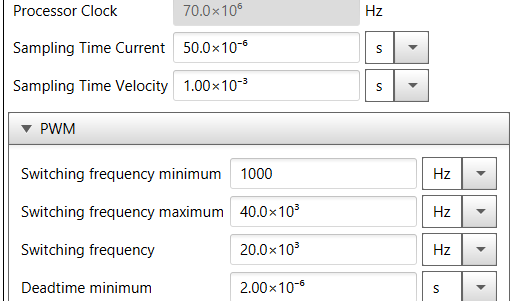
Figure 6.2 shows a screenshot of the Configure page and the three settings that control these rates:
- Sampling time, current — controls the rate at which the bulk of motor control algorithms execute, including the current controller, reference transforms, and position and velocity estimator.
- Sampling time, velocity — controls the rate at which the velocity controller runs
- Switching frequency — controls the PWM switching frequency \(f_{\text{PWM}}\) (ignore minimum and maximum settings)
6.4.1. Effects of changing sampling rate and PWM frequency
Changing the sampling rate or PWM frequency will have some effects on the system design. For the most part, MCAF operation is independent of these choices; some parameters in the generated code will have different scaling factors that depend on sampling rate and PWM frequency, but the net result is approximately the same. The autotuning feature of motorBench® Development Suite will produce approximately the same bandwidths of current and velocity loops.
6.4.1.1. PWM frequency
- Amplitude of ripple current — ripple current amplitudes are proportional to \(VT\over L\), so in general the ripple current is proportional to PWM period, and decreasing the PWM frequency will increase the amplitude of ripple current at harmonics of the PWM frequency.
- Dead-time distortion — increasing PWM frequency will make the dead time a larger fraction of the PWM period. This not only increases dead-time distortion, but also reduces the effective utilization of voltage, since for the same dead time, higher PWM frequency causes the maximum duty cycle to be decreased, and the minimum duty cycle to be increased.
- Switching losses — switching loss energy per PWM period \(E_{sw}\) is dependent on the switching speeds during turn-on and turn-off, and on the switching voltages and currents. Power dissipated in switching loss is equal to \(f_{\text{PWM}} \times E_{sw}\), so increasing switching frequency leads to higher switching power dissipation.
6.4.1.2. Sampling rate
- CPU usage — MCAF runs most of the motor control calculations in firmware once per control loop update, so increasing the sampling rate requires higher CPU usage.
- Current loop gains and bandwidth — Current loop gains (in engineering units: \(K_{ip}\) has units of V/A, and \(K_{ii}\) has units of V/As) will change slightly due to the effects of sampling delay. This is most notable with an aggressive (high-bandwidth) current loop, where increasing the sampling rate lowers the delay from input sampling to output update, and allows a faster current loop bandwidth. If the current loop bandwidth is low (below \(f_{\text{PWM}}/50\)), changes in sampling rate are generally not noticeable.
- Velocity loop gains and bandwidth — Velocity loop gains are affected similarly; increasing the velocity sampling rate will allow a faster maximum bandwidth of velocity loop, but will not have a significant impact if the velocity loop bandwidth is low. In addition, since the velocity control loop is cascaded outside the current loops, aggressive velocity loops will be limited by the current loop bandwidth.
- Diagnostic kernel — the diagnostic kernel runs in the same ISR as the current control loop, so raising the sampling rate will increase the rate at which data is reported to a host PC, and will increase communications bandwidth requirements.
6.4.1.3. Compensating parameters
A number of parameters in the generated code will compensate for changes in PWM frequency and sampling rate. (Tuned gains and customized application parameters are always given in normalized unitless values or engineering units, and are independent of sampling times and PWM frequency, but are converted to fixed-point representation depending on scaling factors that may be dependent on sampling times or PWM frequency.)
- Time delays
- Slew rates, ramp rates, and acceleration rates
- Integrator gains
6.4.2. Restrictions
6.4.2.1. Revision-specific restrictions
In MCAF R6, sampling rates must be locked to specific ratios of the PWM frequency:
- Current sampling time \(T_{s,I}\) must equal the PWM period, so that the bulk of the motor control algorithms run at the PWM frequency (\(f_{\text{PWM}} \times T_{s,I} = 1\))
- Velocity sampling time \(T_{s,\omega}\) must equal 20 times the PWM period, so that the velocity controller runs every 20 PWM periods (\(f_{\text{PWM}} \times T_{s,\omega} = 20\))
These restrictions will be removed in a future version of MCAF.
PWM frequency set in motorBench® Development Suite must match the PWM frequency selected in MCC.
6.4.3. Testing
MCAF R6 code was tested at several PWM frequencies (with current sampling rate locked to PWM frequency and velocity sampling rate locked to 1/20 PWM frequency, following the restrictions listed above):
- 12.5kHz, 20kHz, and 25kHz for confirmation of timing and CPU usage on both the dsPIC33EP256MC506 and the dsPIC33CK256MP508
- 10kHz, 12.5kHz, 16kHz, and 20kHz for general independence of tuning with PWM frequency and current loop sampling rate
- 12.5kHz and 20kHz for detailed verification of step response and estimator independence, for all three position and velocity estimators (ATPLL, PLL, quadrature encoder) on the dsPIC33CK256MP508
Step response tests used the test harness to add a square-wave perturbation to the velocity command, and record the velocity and currents. Figure 6.3 and Figure 6.4 show the current and velocity step response for the ATPLL, logged at 12.5kHz and 20kHz PWM frequencies. Note that the step responses change very little between these cases, as expected.
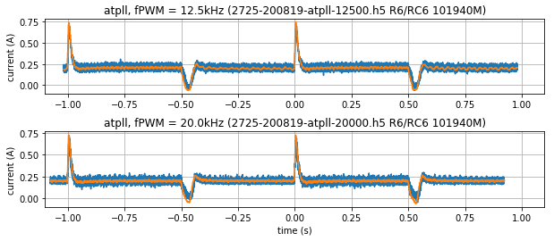
Figure 6.3 Step responses of current to changes in velocity command (orange = q-axis current command, blue = q-axis current)
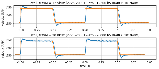
Figure 6.4 Step responses of velocity to changes in velocity command (orange = velocity command, blue = estimated velocity)