5.3.1. AN1292 Phase-locked Loop (PLL)
5.3.1.1. Overview
The sensorless estimator used to estimate position and velocity is essentially the same one described in application note AN1292.
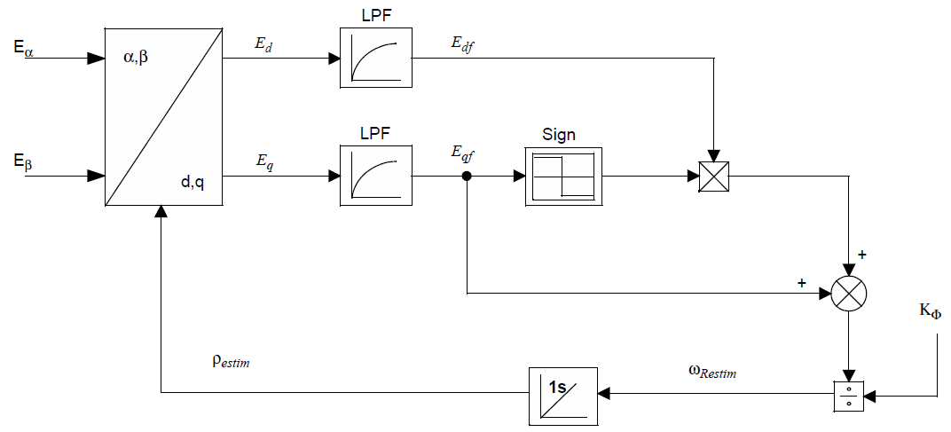
Figure 5.36 AN1292 Phase-locked loop block diagram
Stationary-frame voltages \(V_{\alpha\beta}\) and currents \(I_{\alpha\beta}\) are used to estimate back-emf components \(E_{\alpha\beta}\) using a discrete-time approximation of the equation
The feedback loop shown in Figure 5.36 is then used to rotate \(E_{\alpha\beta}\) into the synchronous (dq) frame to produce an error signal and update the electrical angle \(\theta_e\) (rather than \(\rho_{estim}\) shown in the diagram) used for rotation, where
and \(\rho_{ofs}\) (motor.estimator.pll.rhoOffset in firmware) is a parameter
that defaults to zero, but can be adjusted manually
with real-time diagnostic tools.