5.3. Position and Velocity Estimation
5.3.4. Overview
To facilitate sensorless control of a PMSM, MCAF R5 offers a choice between the AN1292 Phase-locked Loop (PLL) and the Angle-tracking Phase-locked Loop (ATPLL) estimators. In addition to these, support is also provided for Quadrature Encoder through the dsPIC® DSC QEI (Quadrature Encoder Interface) peripheral.
5.3.5. Comparative analysis
5.3.5.1. Summary
| Criteria | AN1292 PLL | QEI | ATPLL |
|---|---|---|---|
| Added in MCAF version | R1 | R1, R4 [1] | R5 [2] |
| Sensors | phase currents, voltages [3] | quadrature encoder | phase currents, voltages |
| Usable at or near zero speed? | no | yes [4] | no |
| Supports significant rotor saliency? | no | yes | yes |
| Sensitivity to motor parameter inaccuracy | moderate | none | low |
Notes
| [1] | Quadrature encoder position has been present since MCAF R1, in a limited form usable for reference comparison only, but not usable for position or velocity feedback. MCAF R4 added commutation offset synchronization to allow its use for commutation. |
| [2] | The ATPLL algorithm is new as of MCAF R5, and may be undergoing some changes in future versions to improve some of its performance characteristics. |
| [3] | As of MCAF R5, phase voltages are inferred from DC link voltage and duty cycle; more accurate results can be obtained from voltage measurements but this is neither required nor supported at present. |
| [4] | Position control and zero-speed control are not presently supported in MCAF. |
5.3.5.2. Additional details
Both the AN1292 Phase-locked Loop (PLL) estimator and the Angle-tracking Phase-locked Loop (ATPLL) estimator algorithms operate on the principle that the steady-state value of the d-axis component of the back emf is equal to zero. Unlike the AN1292 PLL estimator however, the ATPLL estimator includes a PI controller module in its structure. This PI controller needs to be tuned carefully in order to operate stably and satisfactorily over the entire operating velocity range. The AN1292 PLL on the other hand does not have a PI controller and is easier to implement in practice. At the cost of the additional tuning of the PI controller, the ATPLL estimator offers the following advantages over the AN1292 PLL estimator.
One of the advantages offered by the ATPLL estimator is its applicability to motors with both salient and non-salient rotors. By choosing the suitable equations for back-emf calculation for motors with salient and non-salient rotors, the rotor angle and rotor velocity can be correctly estimated by the ATPLL estimator.
The other major advantage offered by the ATPLL estimator over the AN1292 PLL estimator is its robustness with respect to the value of the back-emf constant. For the AN1292 PLL estimator, a discrepancy between the values of the back-emf constant used by the estimator and the actual back-emf constant of the motor results in a steady-state error in the estimated rotor angle. There is no steady state error in the estimated velocity. The ATPLL estimator however is not susceptible to any discrepancy in the back-emf constant and estimates the rotor velocity and angle accurately.
Figure 5.55 shows the actual rotor angle, the estimated angle by the ATPLL estimator and the estimated angle by AN1292 PLL estimator in steady state, when the actual back-emf constant of the motor (\(K_{e\_act}\)) is 20% lower than the value used by the estimator (\(K_{e\_estimator}\)). Figure 5.55 also shows the error in the estimated angle by the AN1292 PLL estimator and the ATPLL estimator in separate plots. It can be observed that there is a significant steady-state error in the estimated angle by the AN1292 PLL estimator, whereas there is no steady-state error in the estimated angle by the ATPLL estimator.
Similar plots are shown in Figure 5.56 where the actual back-emf constant of the motor (\(K_{e\_act}\)) is 20% higher than the value used by the estimator (\(K_{e\_estimator}\)). It can be observed that there is a steady-state error in the estimated rotor angle by the AN1292 PLL estimator in this case as well, however the sign of the error is reversed. The ATPLL estimator however does not show any steady-state error in the estimated rotor angle.
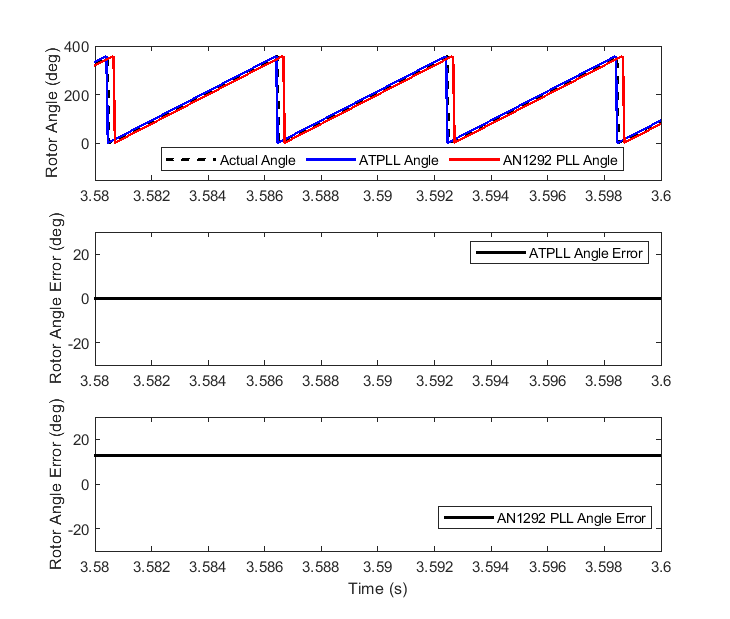
Figure 5.55 Estimated Rotor Angle by the ATPLL and AN1292 PLL for \(K_{e\_act} = 0.8 \times K_{e\_estimator}\)
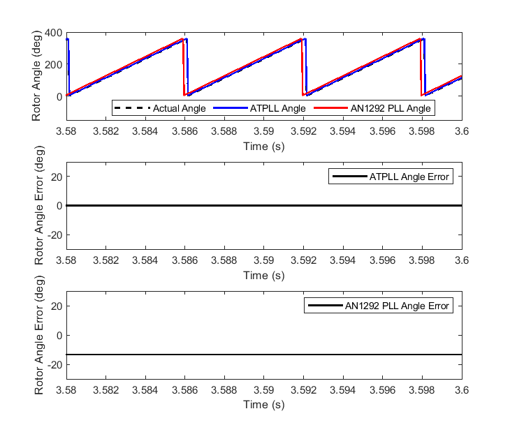
Figure 5.56 Estimated Rotor Angle by the ATPLL and AN1292 PLL for \(K_{e\_act} = 1.2 \times K_{e\_estimator}\)