5.2. Startup
5.2.1. Overview
MCAF includes two different startup methods. Both methods are compatible with sensorless estimators that have a minimum operating speed. Each will operate in closed-loop current control with a forced commutation angle, to bring the motor from a stop to a transition speed where the motor can switch to closed-loop commutation. The only difference between the two methods is how they handle this transition.
5.2.1.1. Method 1: Classic (current decay)
The classic method was originally introduced in MCAF R1, and has been the only available method until MCAF R4. This method transitions by decreasing commanded current until the sensorless estimator’s angle estimate approaches the forced commutation angle, or until the current has dropped below a threshold. This works by allowing the true d-axis current to decrease; as discussed further in the section on phasor analysis.
5.2.1.2. Method 2: Weathervane (reference frame alignment)
The “Weathervane” method was introduced in MCAF R4. This method transitions by simultaneously rotating both the current vector and the reference frame angle, until the sensorless estimator’s angle estimate approaches the forced commutation angle.
5.2.1.3. Choice of startup method
Startup method can be chosen in the Customize page of motorBench® Development Suite. Weathervane provides a faster startup, and is more robust to disturbance torques than the classic method, but it may cause larger torque transients during the transition.
5.2.2. Startup sequence and common elements
Both methods proceed through the following sequence of startup states, and require the motor to be at rest when commencing startup. For most of the startup sequence, velocity control is disabled and closed-loop current control using FOC is enabled, but with a forced commutation angle.
| Startup state | Current | Commutation | Notes |
|---|---|---|---|
Current rampup (RAMPUP) |
Linear increase from
zero to
MCAF_STARTUP_CURRENT |
Fixed,
STARTUP_RAMPUP_ANGLE |
|
Align (ALIGN) |
Fixed,
MCAF_STARTUP_CURRENT |
Fixed,
STARTUP_RAMPUP_ANGLE +
STARTUP_ALIGN_ANGLE_DELTA |
QEI back-emf synchronization can keep startup in this state, and can modify current or commutation angle. |
Slow acceleration (ACCEL0) |
Fixed,
MCAF_STARTUP_CURRENT |
Quadratic (linear velocity ramp)
with constant acceleration
STARTUP_ACCELERATION0 |
Active damping allowed. Cogging torque
may be the dominant mechanical load.
Proceeds when
STARTUP_ACCEL0_VELOCITY_THRESHOLD
reached. (See \(\omega_0\) in
Figure 5.32.) |
Fast acceleration (ACCEL1) |
Fixed,
MCAF_STARTUP_CURRENT |
Quadratic (linear velocity ramp)
with constant acceleration
STARTUP_ACCELERATION1 |
Active damping allowed. Cogging torque
may be the dominant mechanical load.
Proceeds when
STARTUP_ACCEL1_VELOCITY_THRESHOLD
reached. (See \(\omega_1\) in
Figure 5.32.) |
Spin (HOLD) |
Fixed,
MCAF_STARTUP_CURRENT |
Linear with constant velocity | Active damping allowed. Can be held in this state for QEI back-emf synchronization |
Current rampdown
(CURRENT_RAMPDOWN) —
classic method only |
Exponential decay | Linear with constant velocity | Proceeds when angle deviation drops below a threshold, or current drops below a threshold. |
Transition (TRANSITION) —
classic method only |
Output of velocity controller | Output of estimator plus small offset | Velocity controller enabled. Commutation angle from estimator. Offset angle chosen to create smooth transition from previous state. Startup complete when this reaches zero. |
Reference frame alignment
(REF_FRAME_ALIGN) —
weathervane method only |
Fixed,
MCAF_STARTUP_CURRENT |
Linear with constant velocity | Current vector rotated toward d-axis to reflect its actual value. Startup complete when angle deviation drops below a threshold. |
This sequence can also be seen in Figure 5.32:
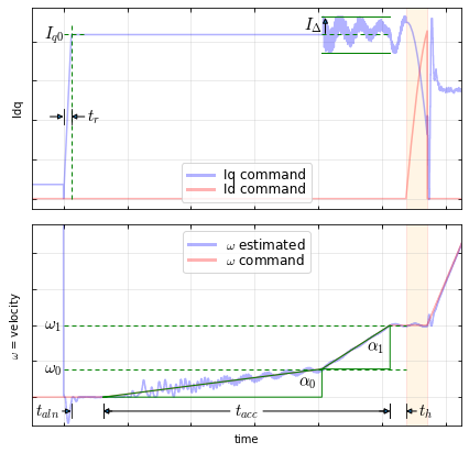
Figure 5.32 Graph of current and electrical frequency in startup sequence. (The Weathervane startup algorithm is shown.)
MCAF R4 and R5 added the ability to adjust various startup parameters in the Customize page of motorBench® Development Suite. See Parameter customization for more information.
5.2.2.1. Startup status codes
To facilitate different startup algorithms which may not share the exact same sequence of states,
a common set of status codes has been created. The status code can be read using MCAF_StartupGetStatus()
and will be one of the following:
MSST_ALIGN— in an “alignment” phase where the motor is being held at constant or slowly-changing electrical angle. The state machine can be held in this state by other algorithms, for example back-emf synchronization.MSST_ACCEL— in an “acceleration” phase where the motor is being accelerated.MSST_SPIN— in a “spin” phase where the electrical angle is being updated at constant frequency. The state machine can be held in this state by other algorithms.MSST_COMPLETE— startup complete.MSST_UNSPECIFIED— startup in another state besides the above.
5.2.2.2. Phasor analysis
Figure 5.33 shows a typical current vector during open-loop commutation. The magnitude of current \(I\) is chosen to be significantly higher than the required torque-producing current \(I_q\), so that the rotor is dragged along and synchronization is maintained. (With this behavior, a PMSM behaves roughly like a stepper motor under microstepping operation.) As a result, most of the current vector is along the d-axis. In MCAF, for the majority of startup, current is applied along the q-axis of the open-loop reference frame, with no d-axis component, and therefore the open-loop reference frame’s q-axis is aligned with the current vector. This means that the angle difference \(\varphi\) between the actual q-axis and the q-axis in software, is typically in the 60 - 90° range when the mechanical torque load on the motor is relatively low.
The two methods work differently to create a relatively smooth transition to closed-loop operation:
- in the classic method, the magnitude of current is reduced. This has the effect of reducing d-axis current while \(I_q\) will remain roughly what is needed to counteract any mechanical torque loads.
- in the weathervane method, the current vector is rotated so that the open-loop reference frame and actual rotor reference frames converge, with most of the applied current along the d-axis and a small portion of it along the q-axis.
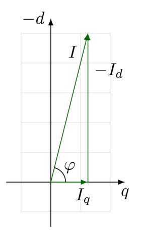
Figure 5.33 Current vector during forced commutation — most of the current is along the d-axis.
To illustrate this more clearly, the Hurst DMB0224C10002 (Microchip #AC300020) was used with an inertia load. Selected program variables were recorded during startup of both methods, with the AN1292 PLL as the estimator.
5.2.3. Classic startup (current decay)
In the classic method, current is decreased, as shown in Figure 5.34. This causes the forced commutation angle to converge towards the angle derived from the estimator, although sometimes this process is slow and requires a very small current.
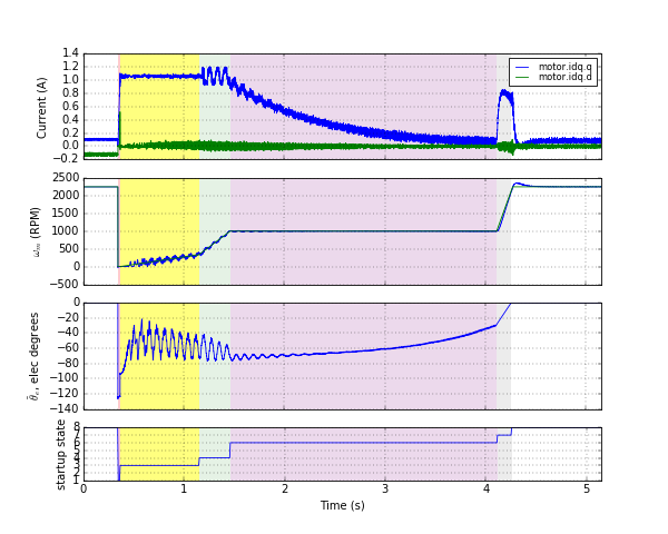
Figure 5.34 Classic startup
The different startup states are highlighted:
- Current rampup (1): red
- Slow acceleration (3): yellow
- Fast acceleration (4): green
- Current rampdown (6): purple
- Transition (7): gray
(Note that the align (2) and spin (5) states are skipped in this example; these states allow QEI back-emf synchronization to occur, but if there is no quadrature encoder or the synchronization has already occurred, then the startup sequence proceeds immediately to the next state.)
5.2.4. Weathervane startup
In the weathervane method, the current vector is rotated, as shown in Figure 5.35.
This method has identical states as in the classic method, except that the reference frame align (state 6, highlighted purple) replaces current rampdown, and there is no transition state at the end of startup.
The reference frame alignment can occur much faster than current rampdown, and does not seem to be affected by the mechanical load of the motor.
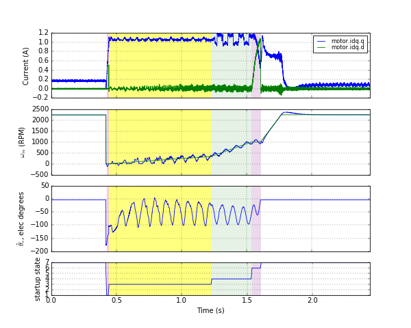
Figure 5.35 Weathervane startup
5.2.5. Active damping
When a PMSM is driven with constant current at a forced commutation angle at constant frequency, its dynamics are roughly a very lightly-damped second-order system. There is a virtual “spring” with restoring torque caused by any misalignment between the rotor magnetic field and the applied stator field. This acts with the rotor inertia to oscillate. These oscillations can grow when the motor is driven at an accelerating frequency, or if the current controller’s error causes sufficient phase lag.
To help control this effect during forced commutation, MCAF contains an “active damping” feature. This modulates the current during forced commutation, by applying a change in current that is proportional to the difference in speed between the commutation frequency and the velocity obtained by the estimator. Active damping is enabled only above a velocity threshold, since for many sensorless estimators it is not possible to obtain accurate estimates at low velocities. (The velocity threshold to enable active damping can be adjusted in the Customize page of motorBench® Development Suite.) This can be seen in Figure 5.34 and Figure 5.35 during the fast acceleration state (highlighted green).
5.2.6. Slow and fast acceleration
The acceleration rate during startup is increased once the velocity reaches a certain threshold. At low speeds, acceleration is lower to avoid cycle slips that can be caused by cogging torque. At higher speeds, the cogging torque occurs at a higher frequency, and this torque ripple has less of an effect on rotor dynamics, so that cycle slips are less likely to occur, and it’s possible to increase velocity more quickly. (Most of cogging torque ripple is absorbed by the rotor and load inertia.)