4.5. Test Harness
The test harness represents several runtime parameters, which, in combination with adjustable parameters used elsewhere in MCAF, can be used to put the controller into certain test modes in order to debug and test proper operation of control algorithms, the board, and/or motor. It is tightly coupled to the design of the FOC modules.
4.5.1. Overview
The test harness includes the features listed below.
- Operating mode — this determines whether the motor controller operates in its normal mode, or with a subset of the controller features, and is used for accretive testing, so that, for example, PWM outputs can be tested first, then three-phase modulation, then the current loop, then the velocity loop.
- Forced state change — this allows the test operator to force certain state transitions
- Overrides — these are boolean flags that determine whether certain features such as commutation angle, DC link compensation, or input velocity command to operate normally or receive input from alternate sources.
- Square-wave perturbation — this adds a square wave signal to either velocity, current, or voltage commands.
- Seizures — Setting an appropriate flag causes either the ISR or the main loop to enter an infinite loop, triggering the watchdog timeout (if enabled). This allows testing of the watchdog timer.
- Intentional stack overflow — Allows testing the hardware stack overflow trap.
- Guards — Test guards prevent accidental activation of test harness features.
- Profiling timestamps — these are 16-bit timer snapshots that can be used for profiling the main control ISR.
Seizures, stack overflow, and guards are features that apply to the MCAF firmware as a whole, whereas the remaining features apply to each motor in the system.
4.5.2. Accretive Testing
Motor control testing should be possible using firmware that is as equivalent as possible (ideally identical) to the intended release firmware. This prevents errors reproducing a problem in the release firmware because it got out of sync with the test firmware.
The MCAF includes built-in test modes to support so-called “accretive” testing at run-time, allowing engineers to start from low-level tests of the power electronics, and work up through verification of open-loop commutation, current control loop, and finally velocity control loop, all without having to recompile the software. This approach is vital, both when bringing up a new circuit board, and when troubleshooting.
4.5.3. Test Harness Parameters
The following table lists test parameters used in various cases. Parameters are
found both in the main motor data structure MCAF_MOTOR_DATA, and the main
system data structure MCAF_SYSTEM_DATA, and are hierarchical (e.g.
motor.testing.sqwave.idq.q for the q-axis current command perturbation shown below).
| Parameter | Description |
|---|---|
motor.testing |
Contains testing parameters per motor |
.sqwave |
Contains parameters for square wave generator |
.halfperiod |
Half-period, in PWM cycles, of the test square wave |
.velocity [1] |
Amplitude of velocity command perturbation |
.idq |
Amplitudes of current command perturbation |
.d |
Amplitude of d-axis current command perturbation |
.q |
Amplitude of q-axis current command perturbation |
.vdq |
Amplitudes of voltage command perturbation |
.d |
Amplitude of d-axis voltage command perturbation |
.q |
Amplitude of q-axis voltage command perturbation |
.value |
square-wave signal, 0 or ±1 (0 to disable all perturbations) |
.overrides |
Bit fields (denoted later in this document as
|
.overrideOmegaElectrical |
Controls value of electrical frequency used during commutation overrides |
.overrideCommutationOnOff |
Allows delays in commutation angle changes, used during commutation overrides |
.maxCount |
Specifies the period of commutation frequency variations |
.threshold |
Specifies the fraction of time where
overrideOmegaElectrical is applied |
.operatingMode |
Controls operating mode of the motor |
.forceStateChange |
Affects state change of primary state machine |
.timestampReference |
Captured timestamp reference for profiling |
.timestamps |
Captured timestamp values for profiling |
systemData.testing |
Contains testing parameters per system |
.flags |
Test flags, including seizure flags for the ISR and main loop, and stack overflow |
.guard |
Enables test harness functionality |
Notes
| [1] | The type of motor.testing.sqwave.velocity is MCAF_U_VELOCITY,
which is a union containing two members, mechanical and electrical.
These have identical value, but may facilitate special treatment in
future real-time diagnostic tools. |
4.5.4. Test Guarding
The presence of test modes does represent a miniscule risk for accidental operation in these modes. If not set intentionally, the only way to enter a test mode is for certain state variables located in RAM to change autonomously. This can be considered an improbable event, with one of the following causes:
- random hardware failures
- software implementation errors
- execution of write-memory commands from the diagnostic kernel,
which are in turn caused by either
- communications errors that somehow reproduce exactly the required data
- malicious sources
Unfortunately, such a change is persistent, and the test modes will not revert back to normal behavior on their own.
4.5.4.1. Test Features in Production: Should They Stay or Should They Go?
This raises a philosophical question: should a test harness remain in production code? There are two schools of thought for run-time test features.
- Test features should be left in place in production code
- Production code is actually the exact code being tested
- In case of an issue observed later (e.g. customer problem), it facilitates understanding of the issue and can even be activated in the field
- Test features should not be left in place in production code
- They can take extra software resources (CPU time, program and data memory)
- In safety-critical systems they increase the risk of unintended behavior
- Code alterations should be removed upon completion of testing
We believe the choice should be left up to the customer; as a future
enhancement, the application framework will facilitate this by allowing removal
of test features either through the code generation process or the preprocessor
(#ifdef). In any case, keeping the alterations used for testing to a minimum is
extremely important: if we test codebase X but deliver codebase Y, any
differences should not be significant with respect to the features being tested,
otherwise they represent a shortcoming of the test process.
4.5.4.2. Implementation of Test Guarding
To mitigate the risk of accidentally entering test modes, an optional guard
mechanism is provided. Essentially, on each ISR cycle the guard is checked and
if not valid, the test parameters are reset to their normal mode of operation.
The guard consists of two memory locations, a key and a timeout
(systemData.testing.guard.key and systemData.testing.guard.timeout). In order for the
guard to be valid, the key must match a given value (0xD1A6 = “DIAG”).
If the timeout has expired, the key is reset to an invalid value
(zero), otherwise the timeout is decremented. If the guard is invalid, the test
parameters are set to their normal conditions. An example of C code to implement
this behavior is shown in Listing 4.2.
#define GUARD_KEY_VALID 0xD1A6
#define GUARD_KEY_RESET 0x0000
if (systemData.testing.guard.timeout == 0)
{
  systemData.testing.guard.key = GUARD_KEY_RESET;
}
else
{
  --systemData.testing.guard.timeout;
}
// repeat the following block for each motor
if (systemData.testing.guard.key != GUARD_KEY_VALID)
{
  motor.testing.overrides = 0;
  motor.testing.sqwave.value = 0;
  motor.testing.operatingMode = OM_NORMAL;
}
The intent is to require minimal execution time, and to disable test modes
unless diagnostic tools are used to maintain those test modes in an active
condition. The guard key should be set manually; the guard timeout can be
automatically set to its maximum value (0xFFFF) periodically by diagnostic
tools; even at 20 kHz, 65536 counts represents 3.2768 seconds and should be
enough time to allow reactivation in time, even if there are OS or communication
hiccups.
The guard timeout mechanism should be optional: publicly-available tools do not yet support the automatic timeout reset, and in some cases the extra program and data memory usage are not warranted.
Note: MCAF R1-R5 implement test guarding but not the test guard timeout mechanism.
4.5.5. Test Harness Architecture
4.5.5.1. Signal Valves
In order to add test mode hooks with minimal impact on the end application, we introduce the concept of a “signal valve” in a block diagram. This is shown in the following example as a circle with an arrow inside it:
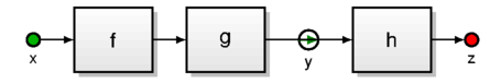
Figure 4.5 Signal valve example
The valve represents a state variable with a choice: in its normal mode of
operation, the valve is “open” and data flows normally through the valve, so
that in the example in Figure 4.5, the signal \(y\) is
determined by input signal \(x\) propagating through
functions f and g. In a
test mode, the block or blocks upstream of the valve are not
executed, and the valve retains its value, so that real-time diagnostic tools
can modify that
value as appropriate.
For example, one way to implement it in C is shown in Listing 4.3:
 int16_t x, y, z;
 bool y_enable = true;
 void step()
 {
   // executed at a regular rate
   if (y_enable)
   {
     y = g(f(x));
   }
   z = h(y);
 }
This gives us a choice between running our control algorithm in its normal mode
of operation (y = g(f(x)); z = h(y);) with x as an input variable,
or in a test mode (z = h(y);) with y as an input variable.
4.5.6. Test harness modes
The behavior shown in Figure 4.6 (reproduced from Figure 4.3) represents the primary signal flow paths used in the motor controller. This does not show the complete functionality of the motor controller; in particular supervisory features like overcurrent and stall detection are not shown. Also note that the shaded area represents a vector controller, and signals within this area have multiple components (dq or alpha-beta or abc).

Figure 4.6 Block diagram of MCAF Field Oriented Control
The behavior of the motor controller can be modified under several different
modes, described in the following sections. Refer to Figure 4.6 for the block
diagram behavior. The modes are enumerated values that can be assigned to the
operatingMode parameter.
4.5.6.1. OM_DISABLED
The OM_DISABLED mode represents a disabled controller with output transistors
set to a “minimal impact state”. Valves V2-V5 are all off.
Active features of the motor controller:
- All feedback computations execute normally, including
- ADC readings
- Park and Clarke transforms
- Commutation angle estimator (if possible)
- Sine and cosine calculation
- Supervisory algorithms (stall detection, overcurrent/overvoltage/etc.)
Inactive features of the motor controller:
- All forward path computations are disabled, including
- Rate limiters
- Current and velocity control loops
- Inverse Park and Clarke transforms
- Zero Sequence Modulation or Space Vector Modulation
PWM Minimal impact state:
- Output transistors are set to a “minimal impact state”, namely:
- upper transistors off
- lower transistors at a minimal duty cycle to maintain bootstrap capacitor charge (or completely off if this is not required)
The behavior in the OM_DISABLED state is best implemented as a separate
state (e.g. STATE_TEST_DISABLE) in the main state machine outside the main state
transitions, with OM_DISABLED forcing entrance to that state from any other
state. Re-entry into other test modes or normal behavior can then be handled in
the state machine, allows exiting of the OM_DISABLED state to occur cleanly.
4.5.6.2. OM_FORCE_VOLTAGE_PWM
The OM_FORCE_VOLTAGE_PWM mode represents a test mode where the PWM outputs are
active and assigned from static motor state variables, shown as \(D_{abc1}\) in Figure 4.6. Valves V2-V5 are all off.
Active/inactive features of the motor controller: Same as OM_DISABLED.
Use case: Testing system behavior with constant or slowly-changing PWM duty cycles.
Motor or other load may or may not be connected.
- Using debug tools, set mode to
OM_DISABLEDfirst- Set \(D_{abc1}\) to desired values
- Set mode to
OM_FORCE_VOLTAGE_PWM
The behavior in the OM_FORCE_VOLTAGE_PWM is best implemented as a separate state
(e.g. STATE_TEST_ENABLE) in the main state machine outside the normal state
transitions, with OM_FORCE_VOLTAGE_PWM forcing entrance to that state from any
other state. Overcurrent, or any other severe fault condition, should cause
entrance to a disabled state that requires manual re-entry into the enabled
state.
Setting OM_FORCE_VOLTAGE_PWM without using OM_DISABLED first is not
forbidden, but may have undesirable consequences, since whichever values were
present in \(D_{abc1}\) are “frozen” at the time of mode switch, unless changed via
debug tools.
4.5.6.3. OM_FORCE_VOLTAGE_ALPHABETA
The OM_FORCE_VOLTAGE_ALPHABETA mode represents a test mode where the PWM outputs
are active along with the ZSM block and inverse Clarke block, which takes its
inputs from static motor state variables, shown as \(D_{\alpha\beta}\) in Figure 4.6. Valves V2-V4
are off; valve V5 is on.
Active/inactive features of the motor controller: Same as
OM_FORCE_VOLTAGE_PWM, but inverse Clarke and ZSM are now active.
Use case: Testing system behavior with the inverse Clarke transform active. (rare)
Otherwise this mode is similar to OM_FORCE_VOLTAGE_PWM and should be handled in
a special state (STATE_TEST_ENABLE) outside the normal state transitions.
4.5.6.4. OM_FORCE_VOLTAGE_DQ
The OM_FORCE_VOLTAGE_DQ mode represents a test mode where the PWM outputs are
active along with the ZSM block, inverse Clarke, and inverse Park block, which
takes its inputs from static motor state variables, shown as \(V_{dq0}\) in Figure 4.6.
Valves V2-V3 are off; valves V4-V5 are on.
Active/inactive features of the motor controller: Same as
OM_FORCE_VOLTAGE_ALPHABETA, but inverse Park, DC link compensation, and
dq-voltage perturbation are now active.
Use case: Testing system behavior with the inverse Park transform active. This represents open-loop sinusoidal voltages applied line-to-line. Commutation angle can either be done through the normal feedback mechanism, or via forced commutation. DC link voltage compensation can be active or inactive.
Otherwise this mode is similar to OM_FORCE_VOLTAGE_PWM and should be handled in
a special state (STATE_TEST_ENABLE) outside the normal state transitions.
4.5.6.5. OM_FORCE_CURRENT
The OM_FORCE_CURRENT mode represents a test mode where the PWM outputs are
active along with the forward path and the current controller, which takes its
input command from static motor state variables, shown as \(I_{dq,\text{ref0}}\) in Figure 4.6.
Valve V2 is off; valves V3-V5 are on.
This can be considered a “torque mode”, since controlling \(I_{dq}\) effectively dictates motor torque. Because of this, unless the input command is small or there is a stiff mechanical load present, the motor will generally accelerate to its full speed.
Active/inactive features of the motor controller: Same as OM_FORCE_VOLTAGE_DQ,
but the current controller and its input filter are now active.
Use case: Testing system behavior with a current loop active. Commutation angle can either be done through the normal feedback mechanism, or via forced commutation.
Otherwise this mode is similar to OM_FORCE_VOLTAGE_PWM and should be handled in
a special state (STATE_TEST_ENABLE) outside the normal state transitions.
Note: Because this is a test mode, the normal motor startup process does not operate, and no automatic transition occurs from open-loop commutation to closed-loop commutation. This mode should either be enabled after the motor startup has occurred, or commutation behavior will have to be managed manually.
4.5.6.6. OM_NORMAL
The OM_NORMAL mode represents the default operating mode of velocity control.
All features are active, including the main state machine.
4.5.7. Interaction with the System State Machine
Figure 4.2 shows the system state machine and its interaction with the operating
mode. If the operating mode is OM_NORMAL, the state machine should revert to its
reset state, where it can safely re-engage in its normal behavior. If the
operating mode is OM_DISABLED, the state machine should enter STATE_TEST_DISABLE
state, where a new test operating mode can put it into the STATE_TEST_ENABLE
state with a clean transition. In order to support certain rare test cases,
direct entry into STATE_TEST_ENABLE is allowed but is discouraged.
4.5.8. Forcing System State Machine Transitions
Operating modes other than OM_NORMAL alter the behavior of the state machine.
In some cases, it is useful to maintain the essential behavior of the state machine,
but cause manual transitions in the state machine to some desired state.
This can be accomplished by setting motor.testing.forceStateChange to one
of the following values:
TEST_FORCE_STATE_RUN— sets theui.runflag totrue, behaving the same way as starting the motor with a button press.TEST_FORCE_STATE_STOP— setsui.runtofalse, behaving the same way as stopping the motor with a button press.TEST_FORCE_STATE_STOP_NOW— setsui.runtofalseand bypasses the time delay in theSTOPPINGstate by causing the coastdown timer to immediately expire, performing an abrupt transition to theSTOPPEDstate. Useful for high-inertia motors where the motor is brought to a stop quickly through external load torques, such as a mechanical brake.
Using motor.testing.forceStateChange is preferable to directly altering
the main motor FSM state (motor.state), since transitions in the state machine
are allowed to happen normally. Setting motor.state directly may cause
initialization steps at the beginning of a state transition to be skipped.
4.5.9. Test Harness Switches (Overrides)
Test harness switches are boolean flags stored in an overrides field.
4.5.9.1. Input Velocity Command Override
If the bitfield overrides:velocityCommand is false, valve V1 is enabled and
the velocity command comes from its normal source.
If overrides:velocityCommand is true, the velocity command is static and may be changed via debug tools.
4.5.9.2. Commutation Override
If the bitfield overrides:commutation is false, commutation angle is computed in its normal manner.
If overrides:commutation is true, the commutation angle is updated automatically with the repetition
of the following behavior (“on-off commutation”):
- for \(k\) PWM cycles, the commutation angle accumulates the commutation frequency \(\omega_{e,\text{override}}\) [2]
- for \(N-k\) PWM cycles, the commutation angle is fixed.
The available values of \(k\) and \(N-k\), and the program variables that control them, depend on the MCAF version, and are detailed in subsections below. There are a number of use cases that can be achieved with this feature; these can be controlled using real-time debug tools to set appropriate program variables.
- Fixed commutation angle — set \(\omega_{e,\text{override}} = 0\), set desired commutation angle.
- Fixed commutation frequency — set \(\omega_{e,\text{override}} \ne 0\), set \(N=1, k=1\).
- Quasi-fixed, slow commutation frequency (since MCAF R3) — set \(\omega_{e,\text{override}} = \pm 1\), set \(N>1, k=1\), for an effective commutation frequency of \(f_{PWM}/N\).
- Commutation angle jumps (since MCAF R3) — set \(\omega_{e,\text{override}} = \Delta\theta\), set \(N\gg 1, k=1\), for a jump angle of \(\Delta\theta\) and a jump frequency of \(f_{PWM}/N\). Setting \(\Delta\theta \approx 60^\circ\) (10923 counts) can achieve quasi-six-step operation during open-loop testing.
- Slew-rate-limited jumps (since MCAF R4) — set \(\omega_{e,\text{override}} \ne 0\), set \(N\gg 1, k>1\). This achieves the behavior shown in Figure 4.7.
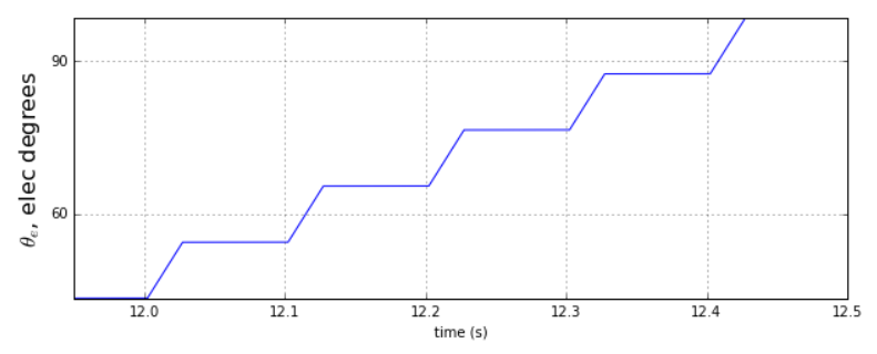
Figure 4.7 On-off commutation for slew-rate-limited jumps
Notes
The transition of commutation angle from forced commutation to normal commutation is an abrupt transition, and is likely to cause transient disturbances in motor current.
| [2] | Commutation frequency \(\omega_{e,\text{override}}\) = motor.testing.overrideOmegaElectrical
has different scaling factor from the velocity values used elsewhere in MCAF, such as
motor.omegaElectrical or motor.testing.sqwave.velocity.
This is done in order to minimize the CPU execution time of the test harness.
The type of motor.testing.overrideOmegaElectrical is MCAF_U_VELOCITY_DTHETA_ELEC_DT;
this type is just an alias for int16_t but it is intended to signify scaling as a change in
electrical angle per control update. With \(N=1, k=1\), a value of 1 count will increment
the commutation angle motor.thetaElectrical by one count on each control update —
for a 20 kHz control ISR, this amounts to ≈ 109.863°/s = 0.30518 Hz;
a value of 32767 counts corresponds to just under 10kHz. |
4.5.9.2.1. MCAF R1 and R2
Only \(k=1,N=1\) is supported.
4.5.9.2.2. MCAF R3
- \(N-1\) is the value of
overrideCommutationDelay. - \(k = 1\) is fixed.
4.5.9.2.3. MCAF R4 and later
- \(N-1\) is the value of
overrideCommutationOnOff.maxCount - \(k\) is the value of
overrideCommutationOnOff.threshold
4.5.9.3. DC Link Voltage Compensation
If overrides:dcLinkCompensation is false, DC link compensation occurs normally.
If overrides:dcLinkCompensation is true, valve V6 is off and DC link
compensation occurs using a value \(R_V\) that can be either manually adjusted or
left at a fixed value.
4.5.9.4. Stall Detect Override
If overrides:stallDetection is false, all logic related to stall detection occurs normally.
If overrides:stallDetection is true, stall detection itself is not changed,
but a detected stall condition is ignored.
This is useful for running certain tests that would otherwise cause a detected stall condition (whether real or false) to trigger a transition in the state machine and disrupt the intended test.
4.5.9.5. Pause at end of open-loop startup
(Added in MCAF R5)
If overrides:startupPause is false, startup occurs normally, and proceeds to closed-loop
commutation.
If overrides:startupPause is true, startup proceeds normally until reaching the HOLD state,
and remains in the HOLD state (fixed current and electrical frequency, under open-loop commutation),
until one of the following conditions is true:
Remain in HOLD — while in the HOLD state, normal state machine behavior continues; possible exit conditions are:
- the
overrides:startupPauseflag is cleared manually, at which point startup will proceed to closed-loop commutation and normal operation. - a STOP input is received (user presses a button in MCLV-2 or MCHV-2)
- a fault is detected
- the
Switch to
OM_FORCE_CURRENT— the force-current test mode may be entered by manually setting the following flags with real-time diagnostic tools:- Set
overrides:commutation, to prevent normal closed-loop commutation once the test mode is reached - Set
motor.testing.operatingMode = OM_FORCE_CURRENT
This will allow operation in a test state, where the normal state machine does not operate.
- Set
Both are useful for debugging or analyzing behavior during open-loop operation.
The switch-to-OM_FORCE_CURRENT behavior is useful for running at a fixed current
and commutation frequency; attempting to start in the OM_FORCE_CURRENT mode
and manually accelerate to some desired commutation frequency can be difficult.
To summarize the differences in these two approaches:
| Remain in HOLD | Switch to OM_FORCE_CURRENT |
|
|---|---|---|
| Can return to normal closed-loop startup | yes | no |
| Current control level value can be changed at runtime? | no | yes |
| Electrical frequency can be changed at runtime? | no | yes |
| Interacts with normal state machine | yes | no |
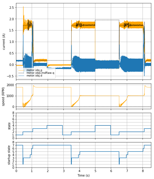
Figure 4.8 Example use of “Remain in HOLD” behavior. (This demonstrates the Weathervane startup algorithm.)
Figure 4.8 shows an example of the “Remain in Hold” behavior with MCAF R5, using the Nidec Hurst DMA0204024B101 motor with the dsPICDEM® MCLV‑2 Development Board:
- From t ≈ 0.4 s to t ≈ 1.0 s, motor is started, and normal startup occurs.
- At t ≈ 3.5 s, the motor is started with
overrides:startupPauseset. - At t ≈ 4.0 s, the motor reaches and remains in the HOLD state (startup state 5).
- At t ≈ 5.0 s, the motor is stopped.
- At t ≈ 6.5 s, the motor is started, and it remains in the HOLD state since
overrides:startupPauseis still set. - At t ≈ 8.0 s,
overrides:startupPauseis manually cleared, so startup proceeds to transition to closed-loop.
(This test used the Forcing System State Machine Transitions feature to start and stop the motor programmatically rather than through the pushbuttons on the MCLV-2.)
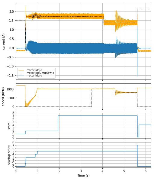
Figure 4.9 Example use of “Switch to OM_FORCE_CURRENT” behavior.
Figure 4.9 shows an example of the “Switch to OM_FORCE_CURRENT” behavior with MCAF R5,
also using the Nidec Hurst DMA0204024B101 motor with the dsPICDEM® MCLV‑2 Development Board:
- t ≈ 0.5 s:
overrides:startupPauseis set manually and the motor is started. - t ≈ 1.0 s: the motor reaches and remains in the HOLD state (startup state 5).
- t ≈ 2.0 s: set
motor.testing.operatingMode = OM_FORCE_CURRENT— note thatmotor.stateswitches toMCSM_TEST_ENABLE = 7 - t ≈ 3.5 s:
motor.testing.overrideOmegaElectricalis set to an appropriate value to maintain speed, andoverrides:commutationis set to stop startup logic from running. (Note that active damping no longer runs, since it is a feature of normal startup.) - t ≈ 4.1 s: current is lowered by 20%
- t ≈ 4.6 s:
motor.testing.overrideOmegaElectricalis lowered by 20%. Note that speed transients are very lightly damped, and cause oscillations in current; this is expected in open-loop commutation. Large transients in electrical frequency can cause cycle slips and loss of lock. - t ≈ 5.6 s: motor is stopped by returning to
OM_NORMALand forcing the motor to stop.
4.5.9.6. Flux control override
(Added in MCAF R6)
If overrides:fluxControl is false, d-axis reference current is computed from the
Flux control module.
If overrides:fluxControl is true, d-axis reference current is static
and may be changed via real-time diagnostic tools.
4.5.10. Perturbation Signals
Perturbation signals may be created using the test harness, which allows step response and disturbance rejection testing for the different controllers.
The state variable sqwave is a structure containing several members to generate
a square wave perturbation signal. The field sqwave.value either remains at 0
(its default value) or toggles back and forth between +1 and -1 every sqwave.halfperiod
test harness updates. For example, if the test harness update is executed during
the control ISR at 20 kHz, and sqwave.halfperiod is 8, then the half-period
is 400 μs and the resulting square wave frequency is 1.25 kHz (= 1/800 μs)
If sqwave.value is set to any other value, it will be limited
in magnitude to 1. The code to do this is found in MCAF_TestPerturbationUpdate:
inline static void MCAF_TestPerturbationUpdate(MCAF_MOTOR_TEST_MANAGER *ptest)
{
    const int16_t value = ptest->sqwave.value;
    /* update test perturbation waveform */
    if (value != 0)
    {
        /*
         * Ensure square wave value maintains sign and is +/- 1:
         * v >> 15 computes as 0 for positive numbers and -1 for negative numbers.
         * To map to +/- 1, we just have to multiply by 2 and add 1
         * (note: (v>>14) + 1 won't work)
         */
        const int16_t valueLimited = (value >> 15)*2+1;

        /*
         * Reverse sign after N cycles (N = sqwave.halfperiod)
         */
        if (++ptest->sqwave.count >= ptest->sqwave.halfperiod)
        {
            ptest->sqwave.value = -valueLimited;
            ptest->sqwave.count = 0;
        }
        else
        {
            ptest->sqwave.value = valueLimited;
        }
    }
}
The sqwave.value field is then multiplied by one of several amplitudes elsewhere
in the code to setup square wave perturbation signals of variable amplitude and
added into the appropriate point of the calculation:
| Signal (see Figure 4.6) | Amplitude variable(s) | Description |
|---|---|---|
| \(\omega_{m,\text{pert}}\) | sqwave.omega |
Mechanical velocity |
| \(I_{dq,\text{pert}}\) |
|
FOC current command |
| \(V_{dq,\text{pert}}\) |
|
FOC voltage command (output of current loop) |
This technique allows all test perturbation signals to be disabled by setting sqwave.value = 0,
keeping the execution time of the test harness to a minimum (including guard processing).
4.5.11. Seizures
To test the watchdog timer, the test harness includes flags that can be set at runtime, to enter an
infinite while (true) loop in either the main loop or ISR. The test guards
prevent accidental activation.
4.5.12. Stack overflow
To test the hardware stack overflow trap, the test harness includes a flag that can be set at runtime, to enter an infinite recursion to cause a stack overflow. The test guards prevent accidental activation.
4.5.13. Profiling Timestamps
An array of 16-bit timestamps is part of the test harness state structure. These timestamps are recorded
in various places for use in profiling the main control ISR via real-time diagnostic tools. Sections
of the state_machine module contain code such as the following:
Listing 4.5 ¶MCAF_CaptureTimestamp(&pmotor->testing, MCTIMESTAMP_STATEMACH_START);
This uses one of the timers to count at the system clock rate, so that the timer value indicates the elapsed system clock time.
The various MCTIMESTAMP_xxxx enum values are defined in test_harness_timestamps.h.
Timestamp recording is disabled by default, but can be enabled via #define MCAF_TEST_PROFILING.
(See errata)
4.5.14. Example use cases
This section shows several use cases and how to achieve those use cases with the test harness described in this document. Our entry assumptions are that in each case:
- We start with normal operation with
systemData.testing.guard.key = 0 - The motor is at rest (not rotating)
- A debug tool is in use which can write variables to the target
- The debug tool can regularly assign
systemData.testing.guard.timeout = 0xFFFFas described in Test Guarding, or the guard timeout feature is not in use - We start each test case by setting
systemData.testing.guard.key = 0xD1A6as described in Test Guarding
4.5.14.1. Fixed-frequency sinusoidal current control
motor.testing.operatingMode = OM_DISABLEDmotor.testing.overrides = TEST_OVERRIDE_COMMUTATIONmotor.testing.overrideOmegaElectrical =[some desired value of electrical frequency]- Set desired dq current (see errata)
motor.testing.operatingMode = OM_FORCE_CURRENT
4.5.14.2. Current/torque control mode
motor.testing.operatingMode = OM_DISABLED- Set desired dq current (see errata)
motor.testing.operatingMode = OM_FORCE_CURRENT
4.5.14.3. Normal operation bypassing the external control (potentiometer)
Note that the normal side effects of state machines and fault handling are still active here (e.g. open-loop → closed-loop transition, stall detection and retry, etc.) since we do not enter a test operating mode.
motor.testing.overrides = TEST_OVERRIDE_VELOCITY_COMMANDmotor.velocityControl.velocityCmd =[some desired value of motor velocity in terms of electrical frequency]
4.5.14.4. Square wave velocity command disturbances to a velocity controller with fixed velocity command
This is the same as the previous case, but with a disturbance.
motor.testing.overrides = TEST_OVERRIDE_VELOCITY_COMMANDmotor.velocityControl.velocityCmd =[some desired value of motor velocity in terms of electrical frequency]motor.testing.sqwave.halfPeriod =[desired value of half period]motor.testing.sqwave.omega =[some desired value of velocity amplitude]motor.testing.sqwave.value = 1(starts the square wave)
4.5.14.5. Square wave current command disturbances to a velocity controller with fixed velocity command
Same as the previous section, but with a disturbance to the d and/or q currents. This case keeps the velocity roughly constant while allowing tests of the current step response. Often this is appropriate since a pure current controller will cause the motor to stall or reach its maximum operating speed and saturate.
motor.testing.overrides = TEST_OVERRIDE_VELOCITY_COMMANDmotor.velocityControl.velocityCmd =[some desired value of motor velocity in terms of electrical frequency]motor.testing.sqwave.halfPeriod =[desired value of half period]motor.testing.sqwave.idq.q =[some desired value of current amplitude]motor.testing.sqwave.idq.d =[some desired value of current amplitude]motor.testing.sqwave.value = 1(starts the square wave)
4.5.14.6. Square wave current command disturbances to a current controller with fixed current command
This is the same as the current control mode, but with a disturbance to the d and/or q currents.
motor.testing.operatingMode = OM_DISABLED- Set desired dq current (see errata)
motor.testing.operatingMode = OM_FORCE_CURRENTmotor.testing.sqwave.halfPeriod =[desired value of half period]motor.testing.sqwave.idq.q =[some desired value of current amplitude]motor.testing.sqwave.idq.d =[some desired value of current amplitude]motor.testing.sqwave.value = 1(starts the square wave)
4.5.15. Implementation Notes
4.5.15.1. Test harness feature support
Certain features described in this section have not been implemented the MCAF test harness, but are planned for future versions:
- Test guarding timeout
- Low-level test modes
- Prior to MCAF R3, the overrides
TEST_OVERRIDE_DC_LINK_COMPENSATIONwas not implemented. Since MCAF R3 it is implemented. - MCAF R3 and R4 have added support for on-off commutation.
4.5.15.2. Test harness errata
Manual adjustment of dq-current in
OM_FORCE_CURRENTis not designed correctly. (DB_MC-1167; Applicability: MCAF R1, R2, R3)MCAF_VelocityAndCurrentControllerStephas the following behavior:- D-axis: Current command prior to rate-limiting may be altered with real-time diagnostics
by adjusting
motor.idqCmdRaw.d. Square-wave perturbation usingmotor.testing.sqwave.idq.dis disabled inOM_FORCE_CURRENT(more generally, whenever the velocity loop is disabled). - Q-axis: Current command prior to rate-limiting may be altered with real-time diagnostics
by adjusting
motor.iqTorqueCmd. Square-wave perturbation usingmotor.testing.sqwave.idq.qis enabled inOM_FORCE_CURRENT(more generally, whenever the current loop is enabled).
- D-axis: Current command prior to rate-limiting may be altered with real-time diagnostics
by adjusting
Profiling with
MCAF_CaptureTimestampmay not work properly with MCC-generated timer calls. (DB_MC-2671; Applicability: MCAF R5) There are two important points here:- For dsPIC33CK devices, the wrong timer is used. This can be fixed by manually changing
MCAF_CaptureTimestamp()in test_harness.h, from usingTMR1_Counter16BitGet()(incorrect) to usingHAL_ProfilingCounter_Get()(correct). - MCC-generated timer functions as of 16-bit libraries version 1.166.0 are not inline functions,
and incur the cost of a function call. (CC16DEV-3543) This will impact the timing measurements.
To workaround, change the implementation of
SCCP1_TMR_Counter16BitPrimaryGet()(dsPIC33CK devices) orTMR1_Counter16BitGet()(dsPIC33EP devices) to aninline staticfunction. Note that this requires the function definition to be in the same translation unit as the call site, so it must be present in either test_harness.h or one of the .h files that is #included whereMCAF_CaptureTimestamp()is called; it cannot be located in a separate .c file.
- For dsPIC33CK devices, the wrong timer is used. This can be fixed by manually changing
4.5.15.3. Modules
| Module | Files | Description | Comments |
|---|---|---|---|
test_harness |
test_harness.ctest_harness.h |
Test harness | |
test_harness_timestamps |
test_harness_timestamps.ctest_harness_timestamps.h |
Test harness logic for profiling execution times |