5.4. Flux control
5.4.4. Overview
The flux control module in MCAF deals with generation of a suitable reference value for the d-axis stator current in a PMSM which is then given as an input to the d-axis current controller. The need for injecting a current component in the synchronous d axis could arise out of multiple requirements as described below.
- In a PMSM, the stator voltage is required to increase with rotor velocity. The dc-link voltage of the inverter, however, puts a limitation on the stator voltage. Other important considerations which do not support increase in the DC link voltage are user safety and motor’s safe operating zone. Many applications require the motor to be operated at velocity higher than its rated value. In order to achieve this while also limiting the stator voltage, motor’s airgap flux is weakened by injecting a negative d-axis stator current in the motor. This operation is called as flux-weakening (FW). Flux-weakening is required for motors with salient as well as non-salient rotors. The FW module in Flux Control calculates a suitable d-axis current reference for the flux-weakening operation (\(I_{d\_fw}\)) at a particular velocity and load.
- The second requirement for the flux control module stems specifically from the motors with salient-pole rotors. In case of salient-pole motors, the reluctance torque (arising out of saliency of the motor) can be made to aid the permanent magnet torque by injecting a negative d-axis current in the motor. This ensures that the motor operates at its maximum efficiency by generating Maximum Torque Per Ampere (MTPA). The MTPA algorithm calculates a suitable reference for the MTPA operation (\(I_{d\_mtpa}\)) for a particular operating point.
5.4.5. Flow chart and details
The flux control module contains implementations of flux-weakening and MTPA. Depending on the requirement, either algorithm can be enabled or disabled independently. The flux-weakening module calculates and returns the d-axis current reference \(I_{d\_fw}\), whereas the MTPA module calculates and returns the d-axis current reference \(I_{d\_mtpa}\). When disabled, either of these algorithms returns a value equal to zero for their respective d-axis current reference. The \(I_{d\_ref}\) generation module then chooses the appropriate value between \(I_{d\_fw}\) and \(I_{d\_mtpa}\) and generates the d-axis current reference \(I_{d\_ref}\) as an input to the current controller. Figure 5.68 shows a flow chart of the overall flux control calculations.
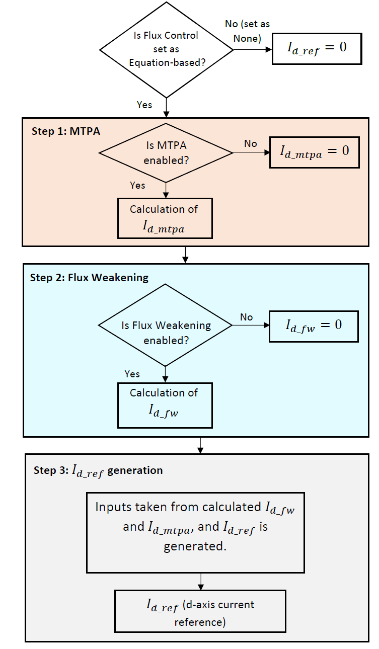
Figure 5.68 Overview of flux control algorithm
- Depending on the requirements, the flux control module can be enabled by setting it to Equation-based. If flux control is disabled by setting it to None, \(I_{d\_ref}\) is made equal to zero. Once enabled, either or both of the MTPA and FW algorithms can be enabled.
- The flux-weakening and MTPA modules calculate \(I_{d\_fw}\) and \(I_{d\_mtpa}\) respectively. In case these modules are disabled, corresponding calculated value is made equal to zero.
- In case the application requires a salient-pole motor to operate beyond rated velocity, both MTPA as well as FW should be enabled. In this case, depending on the region of operation, a correct selection between the d-axis current references calculated by either module is made and that reference is given as an input to the d-axis current controller. Refer to D-axis current reference generation for more details.