5.4.3. D-axis current reference generation
5.4.3.1. Overview
The flux-weakening module calculates the d-axis current reference \(I_{d\_fw}\), whereas the MTPA module calculates the d-axis current reference \(I_{d\_mtpa}\). The \(I_{d\_ref}\) generation module chooses the appropriate value between \(I_{d\_fw}\) and \(I_{d\_mtpa}\) and generates the d-axis current reference \(I_{d\_ref}\) to be given as an input to the current controller.
The q-axis current limit is computed from the value of \(I_{d\_ref}\), to keep the overall motor current within acceptable bounds.
5.4.3.2. Flow chart and description
Figure 5.66 shows a flow chart of the \(I_{d\_ref}\) module. This module takes \(I_{d\_mtpa}\) and \(I_{d\_fw}\) from the MTPA and FW modules, respectively.
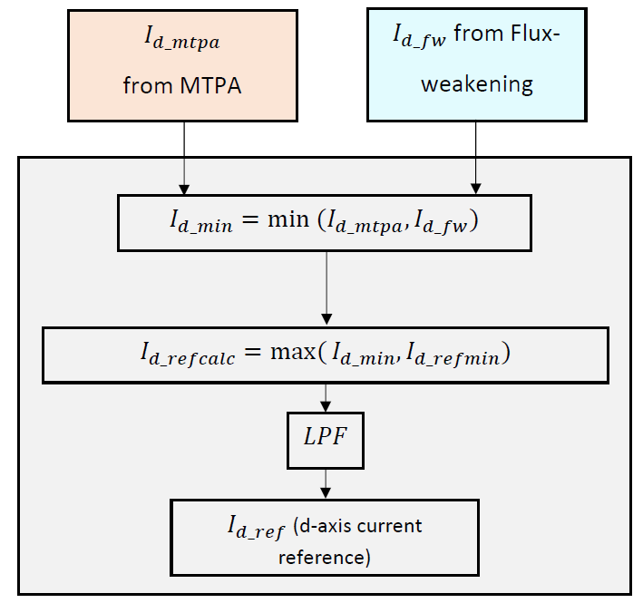
Figure 5.66 \(I_{d\_ref}\) generation flow chart
Possible user inputs for enabling/disabling MTPA and FW are listed in the table below. It is observed that the correct choice for \(I_{d\_ref}\) is the minimum of \(I_{d\_fw}\) and \(I_{d\_mtpa}\) in all cases. Based on this, after calculation of \(I_{d\_fw}\) and \(I_{d\_mtpa}\), the algorithm calculates the minimum of the two (\(I_{d\_min}\)).
User Selection No-FW Region FW Region MTPA Disabled,
FW Disabled
\(I_{d\_mtpa} = 0\), \(I_{d\_fw}= 0\)
\(I_{d\_fw} = I_{d\_mtpa} = 0\)
Does not enter MTPA Disabled,
FW Enabled
\(I_{d\_mtpa} = 0\), \(I_{d\_fw} = 0\)
\(I_{d\_fw} = I_{d\_mtpa} = 0\)
\(I_{d\_mtpa} = 0\), \(I_{d\_fw} < 0\)
\(I_{d\_fw} < I_{d\_mtpa}\)
MTPA Enabled,
FW Disabled
\(I_{d\_mtpa} < 0\), \(I_{d\_fw} = 0\)
\(I_{d\_mtpa} < I_{d\_fw}\)
Does not enter MTPA Enabled,
FW Enabled
\(I_{d\_mtpa} < 0\), \(I_{d\_fw} = 0\)
\(I_{d\_mtpa} < I_{d\_fw}\)
\(I_{d\_mtpa} < 0\), \(I_{d\_fw} < 0\)
\(I_{d\_fw} < I_{d\_mtpa}\)
The calculated \(I_{d\_min}\) is checked against a user-defined minimum value (\(I_{d\_refmin}\)), and if found lower than \(I_{d\_refmin}\), it is limited to \(I_{d\_refmin}\).
The value thus obtained (\(I_{d\_refcalc}\)) is passed through a first-order low pass filter, and the output \(I_{d\_ref}\) gives the d-axis reference as an input to the current controller.
5.4.3.3. Calculation of q-axis current limit
Similar to the limit on the d-axis current, a limit is also imposed on the q-axis current in the motor. In MCAF R6, two different methods of limiting the motor current are implemented viz. rectangular limits and quadratic limits. This choice can be made in Parameter Customization.
Rectangular current limits: In this method, the limits on the d-axis and q-axis currents are defined independently. The limits are specified in Parameter Customization.
Quadratic current limits: In this method, after generation of the d-axis current reference (\(I_{d\_ref}\)), the q-axis current limit is calculated with the help of a quadratic approximation of a circular function as given below.
(5.51)\[\begin{aligned} I_{q\_lim} &= \sqrt{I_{\max}{}^2 - I_{d\_ref}{}^2}\\ &\approx I_{\max}\left(1 - \frac{1}{2} \left(\frac{I_{d\_ref}}{I_{\max}}\right)^2 \right) \end{aligned}\]The calculated q-axis current limit is used by the velocity controller in the FOC path to limit the q-axis current reference.
An illustration of these two methods is shown in Figure 5.67.

Figure 5.67 \(I_{q\_lim}\) calculation as a function of \(I_{d\_ref}\)
The striped curve represents a maximum amplitude of 1.0 normalized to \(I_{\max}\), with thinner circular contours shown in steps of 0.01 amplitude above and below it. A rectangular limit is shown in orange, and a quadratic limit is shown in blue. Limits should be chosen to minimize the excursions above 1.0 amplitude. With the limits shown, a rectangular limit keeps the maximum amplitude below about 1.05 for \(|I_q/I_{\max}| < 0.95,\;|I_d/I_{\max}| < 0.45\); a quadratic limit keeps the maximum amplitude below about 1.03 for \(|I_d/I_{\max}| < 0.7\).