4.3. State Machine
The motor control state machine can be described as a hierarchical state
machine, shown below in Figure 4.2.
The states are shown in blue; the names (MCSM_xxxx) are
the ones used in the application framework code. Transition conditions are shown
as labeled arrows.
This state machine is intended to treat the motor controller at a very high level: rather than concern itself with detailed information about the motor (is a stall occurring? is there an overvoltage?), the state machine is designed around general events like whether a fault has been detected, or whether a start or stop sequence is complete.
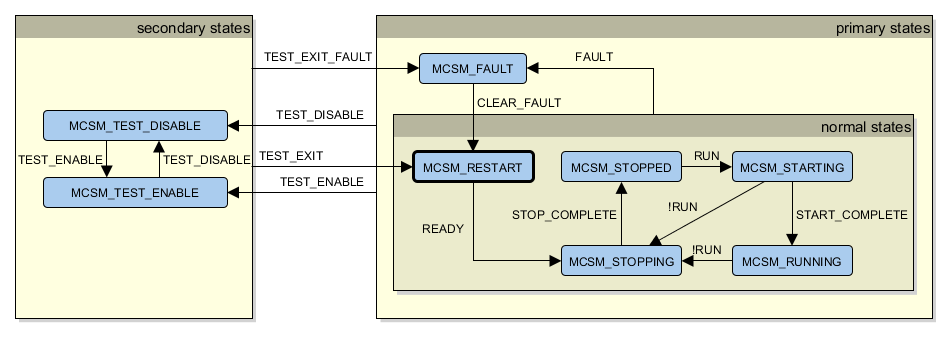
Figure 4.2 Motor controller state diagram
4.3.1. States
These states are divided into subgroups:
- Primary states: all the states except for those used in test operation.
- Normal states: states where a fault is not occurring.
MCSM_FAULT: a fault has occurred.
- Secondary states: all the states used in test operation. These states cause the normal state machine to be ignored, along with some of the fault detection algorithms that may produce false positives when in test modes.
The grouping here forms a hierarchical state machine. For example: any of the
normal states will transition to MCSM_FAULT if a fault has been detected.
(Traditional state machines would require transitions to MCSM_FAULT to be shown
from MCSM_STOPPED, MCSM_STARTING, MCSM_RUNNING, MCSM_STOPPING,
and MCSM_INIT.)
The initial state after power-on reset is MCSM_RESTART. The states are described briefly below:
| State | Description | Assumptions |
|---|---|---|
MCSM_RESTART |
Initial state, entered whenever we power up, or we exit the fault state or a test mode and there is no fault present. Certain run-time calibration activities may be performed. |
It is acceptable to let the motor current stay at zero. |
MCSM_STOPPING |
The motor controller attempts to bring the motor to a complete stop. | The motor may be rotating. |
MCSM_STOPPED |
The motor controller has brought the motor to a complete stop. | The motor is not rotating. |
MCSM_STARTING |
The motor controller attempts to rotate the motor from rest. This may require specialized code, for example in a controller with a sensorless estimator, or in a compressor. | The motor velocity may be zero or small. |
MCSM_RUNNING |
The motor controller attempts to control the motor to a specified control goal, typically regulation of motor velocity. | Control of the motor has been successful so far. |
MCSM_FAULT |
The motor controller has recognized a fault condition, under which it is unable to proceed safely with normal control activities. The motor controller’s actuators are brought to a “minimal impact” state which is deemed acceptable under fault conditions: typically the upper transistors are off, and lower transistors are either off, or set at a small duty cycle. This is a “latched” state: on entry, latch an
error code describing the fault, and display
this code until external intervention occurs
from a |
In general, none. The motor may be rotating or not. The motor may be damaged, the transistors may be damaged, voltages and currents may be out of range, etc. |
MCSM_TEST_DISABLE |
Test state, with transistors set to a minimal impact state. User interface inputs are generally ignored in favor of inputs from diagnostic equipment. |
Either a fault has been detected during a test mode, or the controller is intentionally disabled. |
MCSM_TEST_ENABLE |
Test state, with transistors enabled. Control goal is set by a test operating mode, and is usually different from normal running conditions. For example: one or more control loops disabled, certain fault detections disabled, etc. User interface inputs are generally ignored in favor of inputs from diagnostic equipment. |
The motor controller is being operated in a nonstandard test mode, under controlled conditions, by someone who knows what they are doing. |
4.3.2. Input conditions
The high-level input conditions, shown in the state diagram of Figure 4.2, are used in a mutually exclusive manner (in other words, all conditions starting from a given state are mutually exclusive), and can be defined from more basic conditions as follows:
FAULT: Both of the following are true:operating_fault_detectedis true (see next section)- operating mode is
OM_NORMAL
CLEAR_FAULT:- UI module indicates an intention to clear the latched fault.
READY: OK for the controller to leave theRESTARTstate. True if all of the following are true:- operating mode is
OM_NORMAL operating_fault_detectedis not true- initialization activities for the
RESTARTstate are complete
- operating mode is
RUN: the motor will run. True if all of the following are true:run_requested: UI module indicates an intention for the motor to run.run_permitted: motor is permitted to run; false if a stall condition has been detected.operating_fault_detectedis not true.- operating mode is
OM_NORMAL
START_COMPLETE: True if all of the following are true:RUNis true- a startup completion flag has been set by the startup routine.
STOP_COMPLETE: True if all of the following are true:- a stop completion flag has been set by the stopping routine. (short-term: true always.)
operating_fault_detectedis not true- operating mode is
OM_NORMAL
TEST_DISABLE: True if either of the following are true:- operating mode is
OM_DISABLED test_fault_detectedis true
- operating mode is
TEST_ENABLE: True if all of the following are true:test_fault_detectedis not true- operating mode is any other mode aside from
OM_DISABLEDorOM_NORMAL
TEST_EXIT: True if the operating mode isOM_NORMAL, andFAULTis not trueTEST_EXIT_FAULT: True if the operating mode isOM_NORMAL, andFAULTis true
In some ways it may be easier to think about a prioritized implementation of state transitions, which would probably look like this:
if (operating_mode != OM_NORMAL)
{
  if (operating_mode == OM_DISABLED || test_fault_detected)
  {
    next_state = MCSM_TEST_DISABLE;
  }
  else
  {
    next_state = MCSM_TEST_ENABLE;
  }
}
/* primary states begin here... */
else if (operating_fault_detected && this_state != MCSM_FAULT)
{
  next_state = MCSM_FAULT;
}
else
{
  /* normal states */
  switch (state)
  {
    case MCSM_TEST_DISABLE:
    case MCSM_TEST_ENABLE:
      next_state = MCSM_RESTART;
      break;
    case MCSM_RESTART:
      if (ready)
      {
        next_state = MCSM_STOPPING;
      }
      break;
    case MCSM_STOPPING:
      if (stop_complete)
      {
        next_state = MCSM_STOPPED;
      }
      break;
    case MCSM_STOPPED:
      if (run)
      {
        next_state = MCSM_STARTING;
      }
      break;
    case MCSM_STARTING:
      if (!run)
      {
        next_state = MCSM_STOPPING;
      }
      else if (start_complete)
      {
        next_state = MCSM_RUNNING;
      }
      break;
    case MCSM_RUNNING:
      if (!run)
      {
        next_state = MCSM_STOPPING;
      }
      break;
    case MCSM_FAULT:
      if (clear_fault_latch)
      {
        next_state = MCSM_RESTART;
      }
      break;
    default:
      next_state = MCSM_RESTART;
  }
}
4.3.3. Miscellaneous state machine issues
4.3.3.1. Startup
While in the MCSM_STARTING state, a specialized startup process
is used to bring the motor from rest to a sufficient speed
for the sensorless estimator to provide commutation information.
During this state, the velocity loop is disabled, and commutation angle is
slowly accelerated in an open-loop fashion, instead of using the commutation
angle from the sensorless estimator.
See the section on startup for more information.
4.3.3.2. Fault detection
Fault detection behaves slightly differently, depending on whether the system is in a test state or a normal mode of operation.
test_fault_detected: In test states, we want to be more lenient in allowing requested operations, so this flag is true only when any of the most severe faults are true; these include things like hardware overcurrent, software overcurrent, overvoltage, etc.operating_fault_detected: In normal operating modes, we want to be more conservative, and stop operation under a wider set of conditions. This includes all of the faults used intest_fault_detected, along with other faults not included intest_fault_detected, such as stall retry count exceeded.This allows detection techniques to be used in normal operating modes, but remain disabled in test modes, so that they do not interfere with tests that might otherwise trigger a fault. Certain heuristic detection techniques belong here, especially if they make assumptions about how the motor is operating (e.g. always in velocity control mode, always rotating in one direction, smoothly-changing velocity commands, etc.) or there is some uncertainty about whether the detection technique can avoid false positives.
Both fault detection schemes are latched, requiring outside action to clear them (for example, a UI button press for the primary states, diagnostic tool action for the test states).
4.3.4. Implementation Notes
The function MCAF_SystemStateMachine_StepIsr() is the main entry point for
the system state machine. The approach used in this function is to execute
these subtasks:
- First execute critical tasks common to all states —
MCAF_MotorControllerOnAllStates() - Determine next state —
MCAF_FSM_DetermineNextState()andMCAF_FSM_DetermineNextStateTestMode() - Dispatch to the appropriate state —
MCAF_FSM_Dispatch() - Finally execute noncritical tasks common to all states —
MCAF_MotorControllerOnAllStatesLowPriority()
Field-oriented control tasks are executed in
MCAF_FocStepIsrFeedbackPath()— This function is executed in all states and includes feedback calculations such as Park/Clarke transforms and position/velocity estimation.MCAF_FocStepIsrForwardPath()— This function is executed in states when motor control is active, and includes both the controllers and other forward path elements such as the inverse Park/Clarke transforms and space vector modulation.
The function MCAF_SystemStateMachine_StepMain() executes low-priority
tasks for the system state machine. At this time, the only such task
is selecting LED patterns for the external interface
to indicate motor direction and state machine state.
4.3.4.1. Implementation notes for stall detection and recovery:
A detection of stall would cause the run_permitted flag to be false, and
therefore bring the motor from the STARTING or RUNNING states into
the STOPPING state. It would not change the run_requested flag from the UI.
Stall detection / recovery need to keep track of a retry count, just as in
the existing implementation; when the retry count exceeded a threshold, the
“stall retry count exceeded” fault would be produced, and the FAULT state
entered.
4.3.4.2. Other implementation notes
State machine functions in each state, and for transitions, should not be called
except from the main state machine update function MCAF_FSM_Dispatch().
The approach used in the MCAF
is to bring each of these functions out as inline functions, for code modularity and
maintainability, but not run-time modularity (treat it as one large function at
runtime).
4.3.4.3. Modules
| Module | Files | Description | Comments |
|---|---|---|---|
parameters/startup_params |
parameters/startup_params.h |
||
startup |
startup.cstartup.hstartup_types.h |
Motor startup including the transition from open-loop commutation to closed-loop commutation | |
state_machine |
state_machine.cstate_machine.hstate_machine_types.h |
Top-level state machine |