5.3.2.3.4. Pullout torque method
5.3.2.3.4.1. Overview
At startup, when the motor is spinning in open loop, the rotor lags the voltage vector at an unknown angle. This is because there is more than required current to meet the load torque. In other words there is a non-zero component of the \(I_d\) current. When the current magnitude is reduced gradually the value of \(I_d\) automatically goes towards zero with \(I_q\) remaining the same until the pullout torque angle is reached. The raw reading from the QEI position counter at the instance of pullout corresponds to \(\pi/2\) plus a small load angle behind the voltage vector depending on the the direction of rotation. This reading is called ‘pullout position’ in equation 5.25. The rotor offset is calculated as
The load angle is insignificant owing to very small currents (\(I_d=0\) at pullout) during no load and lower speeds.
The critical factor therefore with this approach is that the \(T_{fr}/J\) value of the mechanical parameters must be high enough to bring the motor to standstill unassisted in a few seconds approximately. If it takes several seconds other methods should be explored.
The startup sequence’s “SPIN” state (where the rotor has been accelerated to the open loop max. speed) is utilized to allow a suitable settling time to reach mechanical equilibrium, and at the end of this time, the current \(I_q\) is reduced to the point of pullout when the pullout position which is the difference between the applied commutation angle (\(\tan^{-1} V_{\alpha\beta}\)) and the raw encoder count is computed. Once the rotor offset is computed actual rotor position is computed while running as
5.3.2.3.4.2. Limitations
When the rotor is approaching the pullout offset relative to commutation angle, the electromagnetic torque is just enough to balance the load torque. Any minor disturbance or cogging effects could stall the motor beyond recovery. This requires the rotor not be subjected to any torque disturbances during measurement. This method is robust to steady frictional or viscous torques, however.
This method of offset measurement has certain drawbacks. High inertia motors will not show rapid changes in speed when \(I_d\) approaches zero. Since the firmware looks for an abnormal rate of increase in this relative angular position there will be larger errors for motors with high inertia. The method relies on gradual current reduction and multiple retries for accurate pullout detection which consumes a lot of time. The pullout method typically takes 30-45 seconds to complete.
Cogging torque effects, limited resolution of sensors, and slower rotational speeds can all cause the relative angle between the voltage vector and QEI position counter to abruptly change which poses challenges to the filtering software.
5.3.2.3.4.3. Practical implementation issues
The pullout slip threshold was chosen to keep the absolute error for a wide range of motors within limits. With motors having low inertia the error will be on the positive side and for ones with high inertia the error is on the negative. A future implementation could configure the velocity threshold used to detect pullout to the motor, which will further reduce the absolute error in most cases.
The time it takes to complete the measurement is based on 4 trials which makes the measurement duration high. With lower resolution encoders a larger number of trials are needed for the same accuracy. For example, with a 250 line encoder 8 re-tries had better results.
Since a retry has to be started before the motor actually stalls, the exact point of pullout is only approached and never attained which makes this method always have some small non-zero error.
5.3.2.3.4.4. Example data
The tests are done on 4 different motors equipped with an encoder and Index. The index is only used to compute the difference between measured and precomputed offsets for the motor. This value is used only for test purposes.
Figure 5.48 shows the use of the pullout method with the Anaheim Automation BLWS232D-24V-1350-1024SI5, which has a 1024-line encoder and fairly low cogging torque. For this motor, the pullout method works very well with low error. The yellow highlight shows the speed ramp up states (speed not shown), once speed has stabilized in the “SPIN” state, \(I_q\) current is reduced until it reaches the maximum value of pullout torque angle. During the first iteration the current reduction happens at a higher rate and is primarily to arrive in the proximity of the pullout. The subsequent iterations will then repeat the same procedure at a much reduced rate for better accuracy. The plot shows 4 more re-tries, the results of which are averaged to obtain the commutation offset. Note \(\Delta \theta _e\) goes close to 0 after the retry stage in each of the plots when the “SPIN” state is completed.
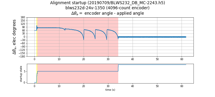
Figure 5.48 Pullout method with BLWS232D-24V-1350-1024SI5
Figure 5.49 shows the use of the pullout method with the Anaheim Automation BLY342D-24V-3200-1024SI5, which has a 1024-line encoder and substantial cogging torque.
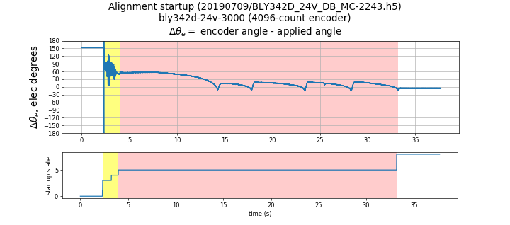
Figure 5.49 pullout method with BLY342D-24V-3000-1024SI5
Figure 5.50 shows the use of the pullout method with the Anaheim Automation BLY171D-24V-4000, which has a 4096-line encoder and almost no cogging torque.
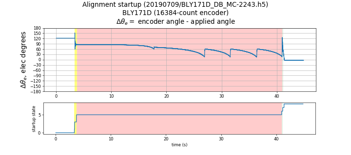
Figure 5.50 Pullout method with BLY171D-24V-4000
In this case due to lesser inertia the default slip threshold results in detecting pullout late or past the actual pullout point. This results in the errors having an opposite sign ( see Table 5.4) compared to the other motors for which the slip threshold is optimal. This motor is an example for a larger value of the slip threshold.
5.3.2.3.4.5. Accuracy and repeatability tests
The pullout method was tested with MCAF R4, and the resulting commutation offset from index
(motor.estimator.qei.position.commutationOffsetFromIndex) was compared against a reference
method using open-circuit voltage measurements of the motor terminals with the motor
rotated mechanically at constant speed.
Table 5.4 describes the results. In each case, 8 iterations of the pullout method were performed. Each motor was tested in both directions which are indicated by CW and CCW suffixes. All motors were tested with the default slip threshold value.
| mean \(\tilde\theta_{ofs}\) | max \(\tilde\theta_{ofs}\) | stdev \(\hat\theta_{ofs}\) | span \(\hat\theta_{ofs}\) | Test case |
|---|---|---|---|---|
| -0.15° | 0.20° | 0.03° | 0.09° | BLWS232D-24V-1350_CW-1024SI5 |
| 0.43° | 0.47° | 0.03° | 0.10° | BLWS232D-24V-1350_CCW-1024SI5 |
| 4.68° | 4.87° | 0.19° | 0.52° | BLY171D-24V-4000_CW with 4096-line encoder |
| -4.52° | 4.67° | 0.13° | 0.29° | BLY171D-24V-4000_CCW with 4096-line encoder |
| -1.05° | 1.24° | 0.09° | 0.30° | BLY342D-24V-3000_CW-1024SI5 |
| 0.77° | 0.89° | 0.23° | 0.72° | BLY342D-24V-3000_CCW-1024SI5 |
| -1.03° | 1.11° | 0.04° | 0.12° | BLY342D-48V-3200_CW-1024SI5 |
| 1.04° | 1.12° | 0.06° | 0.20° | BLY342D-48V-3200_CCW-1024SI5 |
The error metrics are as follows:
- mean \(\tilde\theta_{ofs}\) — mean value of the commutation offset difference between the pullout method and the reference method
- max \(\tilde\theta_{ofs}\) — maximum value of the commutation offset difference between the pullout method and the reference method
- stdev \(\hat\theta_{ofs}\) — standard deviation of commutation offset estimated by the pullout method
- span \(\hat\theta_{ofs}\) — difference between minimum and maximum commutation offset estimated by the pullout method
Motors with low inertia, such as the BLY171D-24V-4000, could benefit from a higher value of slip threshold for better accuracy. Please refer to the parameter customization notes on pullout slip threshold for more information.