5.3.2.3.3. Align-and-sweep method
5.3.2.3.3.1. Overview
The align-and-sweep method is a slight modification to the align method. Instead of a fixed angle during the align state, the applied electrical angle is slowly rotated for one full mechanical cycle in both directions, and a commutation offset is estimated by taking an average angle difference between applied and measured angle over these two cycles. (The same calculation is used as in the align method, but a mean value over many measurements is used instead of a single measurement.) The intent is that by covering a complete mechanical rotation, angle variations due to cogging torque would be averaged out. Averaging over both positive and negative rotation cancels out most of the impact of friction torque.
The resulting commutation offset has extremely good accuracy and repeatability behavior. It takes more time, however, than the simple align method, and is slightly more complex.
5.3.2.3.3.2. Limitations
The limitations of the align method, namely torque disturbances and semistable equilibrium, are less of an impact in the align-and-sweep method. Disturbance torques can still cause measurement error, however, and should be avoided.
5.3.2.3.3.3. Practical implementation issues
Rampup and align angles are not particularly important to this algorithm.
With this method, initial alignment transients need to settle before making measurements. Alignment transients occur with any acceleration, so reversing the rotation direction causes a transient, as well as changing from no motion to the slow electrical rotation.
To manage these transients, the align-and-sweep method includes “setup” intervals. During the setup intervals, angular frequency is kept constant and allows alignment transients to settle, prior to the beginning of measurement intervals.
5.3.2.3.3.3.1. Selection of rotation rate
MCAF R4 allows three choices of rotation rate during the align-and-sweep method: 1, 2, and 4 counts per control ISR, where each count is 1/65536 of an electrical cycle ≈ 0.0055°. The 4-count option is fastest, and the 1-count option is slowest.
There are tradeoffs between rotation speed and accuracy. Running the align-and-sweep method at higher rotation speeds will complete the measurement more quickly, but will experience larger angle fluctuations, and the resulting angle offset may have more random errors. Slower rotation speeds will improve accuracy, but will increase the measurement time.
5.3.2.3.3.3.2. Calculations involving angles
Averaging measurements of angles, which involve wraparound semantics, can be tricky, since the calculations involve “good” and “bad” overflows that must be distinguished, and avoiding overflow does not necessarily guarantee a correct result. As an example, suppose we wish to find the average value of the following sequence of angles: +176°, -170°, -174°, -167°, +177°. A simple mean value calculation will come up with -31.6°, which is not correct. There are at least two ways to handle this issue:
- Unwrap the angles prior to averaging. “Unwrap” here means to translate small angle changes so that the angle values remain equivalent, but are adjusted by an integer number of rotations so that there is never a jump across the branch point of ±180°. In the example sequence above, unwrapping the angles would produce the sequence +176°, +190°, +186°, +193°, +177°, which yields the correct average of +184.4° = -175.6°.
- Offset the angles prior to averaging. One simple way to avoid jumps across the branch point is to move the branch point by a fixed offset. We can use an offset that subtracts out the first measurement, and as long as the net change in angle from this first measurement stays below 180°, then it will not cross the branch point. In the example sequence above, an offset of -176° (the negation of the first measurement) is used, and the resulting sequence becomes 0, +14°, +10°, +17°, +1°, which has an average of +8.4°; add back the first measurement of +176° and we get +176° + 8.4° = -175.6°.
In the align-and-sweep method, the offset approach is used rather than the unwrap approach; the offset approach is less complex, and requires less memory to avoid overflow.
5.3.2.3.3.3.3. State machine
To manage the setup and measurement intervals, the align-and-sweep method includes a simple state machine that runs through a fixed sequence:
START— records initial angle measurement to use as a reference point for avoiding wraparound problems.FORWARD_SETUP— begins slow rotation of applied electrical angle in a positive direction, over a specified angle interval.FORWARD_MEASURE— computes and accumulates the angle difference between the applied angle and the measured encoder angle. Continues slow positive rotation over one complete mechanical cycle.REVERSE_SETUP— begins slow rotation of applied electrical angle in a negative direction, over a specified angle interval.REVERSE_MEASURE— computes and accumulates the angle difference between the applied angle and the measured encoder angle. Continues slow negative rotation over one complete mechanical cycle.INACTIVE— leaves electrical angle alone, allows the startup sequence to continue past the align state.
While in all states other than the INACTIVE state, the
startup sequence is held in the align state
in order to complete the synchronization steps.
5.3.2.3.3.4. Example data
Figure 5.45 shows the use of the align-and-sweep method
with the Anaheim Automation BLWS232D-24V-1350-1024SI5, which has a 1024-line
encoder and fairly low cogging torque.
For this motor, the align-and-sweep method works very well, with low error.
The yellow highlights show the two setup states (FORWARD_SETUP and REVERSE_SETUP),
and the green highlights show the two measurement states
(FORWARD_MEASURE and REVERSE_MEASURE). The setup states
allow transients to settle down sufficiently before measurement.
This motor shows only around ±10° of fluctuations
due to cogging torque, and the fluctuations average out.
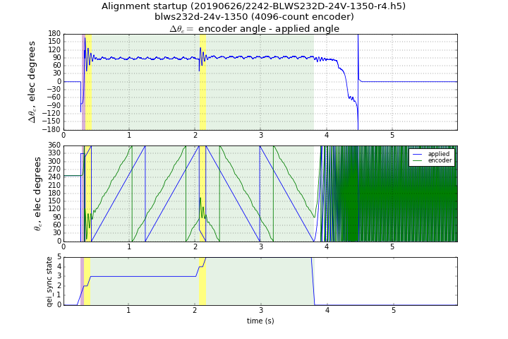
Figure 5.45 Align-and-sweep method with BLWS232D-24V-1350-1024SI5, sweep rate = 4 counts per control ISR
The BLY342D-24V-3000-1024SI5 has high cogging torque and presents more of a challenge for back-emf synchronization. Figures 5.46 and 5.47 show the align-and-sweep method in action with this motor; the two figures show different sweep rates. Angle fluctuations can be over 60° peak-to-peak, and the effect of Coulomb friction is easily visible as a direction-dependent offset. The lower sweep rate helps reduce angle fluctuations, and produces a more accurate result, at the cost of the measurements taking longer.
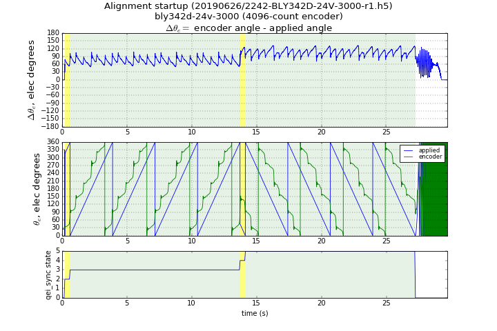
Figure 5.46 Align-and-sweep method with BLY342D-24V-3000-1024SI5, sweep rate = 1 counts per control ISR
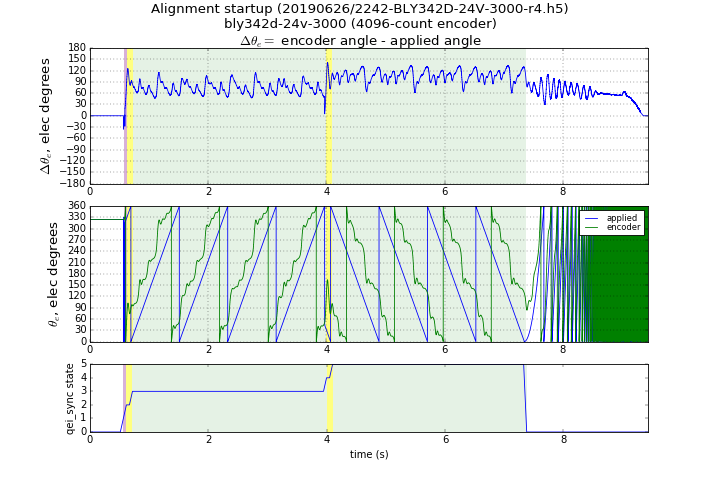
Figure 5.47 Align-and-sweep method with BLY342D-24V-3000-1024SI5, sweep rate = 4 counts per control ISR
5.3.2.3.3.5. Accuracy and repeatability tests
The align-and-sweep method was tested with MCAF R4, and the resulting commutation offset from index
(motor.estimator.qei.position.commutationOffsetFromIndex) was compared against a reference
method using open-circuit voltage measurements of the motor terminals with the motor
rotated mechanically at constant speed.
Table 5.3 describes the results. In each case, 16 iterations of the align-and-sweep method were performed. (Initial conditions were identical but do not have a significant influence over the resulting estimated offsets since the method rotates the motor over the entire mechanical rotation.) Each motor was used with a dsPICDEM® MCLV‑2 Development Board, with default current limit of 2.29A, and default startup current at 91% of the current limit = 2.08A.
| mean \(\tilde\theta_{ofs}\) | max \(\tilde\theta_{ofs}\) | stdev \(\hat\theta_{ofs}\) | span \(\hat\theta_{ofs}\) | r | Test case |
|---|---|---|---|---|---|
| 0.02° | 0.03° | 0.007° | 0.02° | 2 | BLWS232D-24V-1350-1024SI5 |
| 0.03° | 0.06° | 0.013° | 0.06° | 4 | BLWS232D-24V-1350-1024SI5 |
| 0.06° | 0.08° | 0.010° | 0.03° | 2 | BLY171D-24V-4000 with 4096-line encoder |
| 0.05° | 0.07° | 0.009° | 0.03° | 4 | BLY171D-24V-4000 with 4096-line encoder |
| 0.08° | 0.10° | 0.016° | 0.07° | 1 | BLY342D-24V-3000-1024SI5 |
| 0.18° | 0.22° | 0.016° | 0.07° | 2 | BLY342D-24V-3000-1024SI5 |
| 0.15° | 0.47° | 0.195° | 0.58° | 4 | BLY342D-24V-3000-1024SI5 |
| 0.08° | 0.10° | 0.008° | 0.03° | 2 | BLY342D-48V-3200-1024SI5 |
| 0.18° | 0.22° | 0.029° | 0.12° | 4 | BLY342D-48V-3200-1024SI5 |
The error metrics are as follows:
- mean \(\tilde\theta_{ofs}\) — mean value of the commutation offset difference between the align-and-sweep method and the reference method
- max \(\tilde\theta_{ofs}\) — maximum value of the commutation offset difference between the align-and-sweep method and the reference method
- stdev \(\hat\theta_{ofs}\) — standard deviation of commutation offset estimated by the align-and-sweep method
- span \(\hat\theta_{ofs}\) — difference between minimum and maximum commutation offset estimated by the align-and-sweep method
All of the motors were able to produce estimates with excellent repeatability at 4 counts/ISR sweep rate, with the exception of the BLY342D-24V-3000-1024SI5, which showed degraded accuracy at 4 counts/ISR compared to 2 counts/ISR.