5.3.2.3.2. Align method
5.3.2.3.2.1. Overview
In the absence of load torques (cogging, friction, disturbance), if a fixed αβ-frame stator current vector is applied, the motor will align along the d-axis, since this reaches a point of equilibrium where the electromagnetic torque is zero.
The align method of back-EMF synchronization uses this method for a simple and generally-reliable method of obtaining a commutation offset that is accurate within a few electrical degrees for many motors.
There are, however, subtleties with this method, especially when used with motors that have substantial cogging torque.
If there are load torques when using the align method, the motor will reach a point of equilibrium with an electrical-angle offset \(\tilde{\theta}\) from the d-axis such that \(T_{load} + \frac{3}{2}K_eI\sin\tilde{\theta} = 0\), in other words, \(\tilde{\theta} = -\sin^{-1}\dfrac{T_{load}}{\frac{3}{2}K_eI}\). Cogging/detent torque for low-cost motors may be in the range of 5-10% of continuous rated torque plus 1-3% for friction, so if we use a current I equal to continuous rated current we should expect on the order of \(\tilde{\theta} = \sin^{-1} 0.13 \approx 7.5^{\circ}\) worst-case error. Oversized motors, where the drive cannot deliver current to achieve continuous rated torque, will have larger errors. (example: if total load torque is 13% continuous rated torque, and the drive can deliver 50% continuous rated torque, then we should expect arcsin(13/50) ≈ 15.1° worst-case error.)
The startup sequence’s “align” state (where the current vector magnitude and angle are fixed) is utilized to allow a suitable settling time to reach mechanical equilibrium, and at the end of this time, the difference between the applied commutation angle and the encoder count is computed and used to obtain a commutation offset.
5.3.2.3.2.2. Limitations
- Continuous torque disturbances can prevent mechanical equilibrium
- There is a semistable equilibrium point (locally stable, globally unstable) around \(\tilde\theta = 180^\circ\) where the cogging torque pulls the rotor towards a particular detent position, and the electromagnetic torque is small enough that it cannot pull the rotor out of the detent unless a different commutation angle is applied.
5.3.2.3.2.3. Practical implementation issues
The angles used in the rampup and align states of startup sequence are important, particularly the angle shift: a different commutation angle can be applied during the rampup and align states, to improve the ability of the align method to overcome torque detents and keep from getting stuck at a semistable equilibrium point.
A more in-depth discussion of angle shift is shown below in the section containing example data.
MCAF applies current during the align phase along the q-axis, not the d-axis, so the estimated commutation offset has a \(\pm 90^\circ\) offset from the angle difference between applied commutation electrical angle and measured encoder electrical angle at the end of the align phase. The sign of this \(\pm 90^\circ\) offset depends on the sign of the q-axis current used. (Negative q-axis current is applied during startup when the motor is started in the reverse direction.) In other words, \(\hat\theta_{ofs} = (\theta_{enc} - \theta_{e}) + 90^\circ \operatorname{sgn} I_q\) where the angle subscripts ofs, enc, and e refer to commutation offset, encoder angle (in electrical terms), and forced electrical angle, respectively.
5.3.2.3.2.4. Example data
Figure 5.39 shows the use of the align method with the Anaheim Automation BLWS232D-24V-1350-1024SI5, which has a 1024-line encoder and fairly low cogging torque. For this motor, the align method works very well, with low error. The yellow highlight shows the current rampup state (current not shown), at an applied electrical angle \(\theta_0 = 0^\circ\), and the green highlight shows the align state, at an applied electrical angle \(\theta_1 = 30^\circ\). The motor takes roughly 0.15 seconds to settle to equilibrium, so the align time of 0.5s leaves plenty of time to reach an encoder angle of 120°, which is 90° ahead of the applied electrical angle.
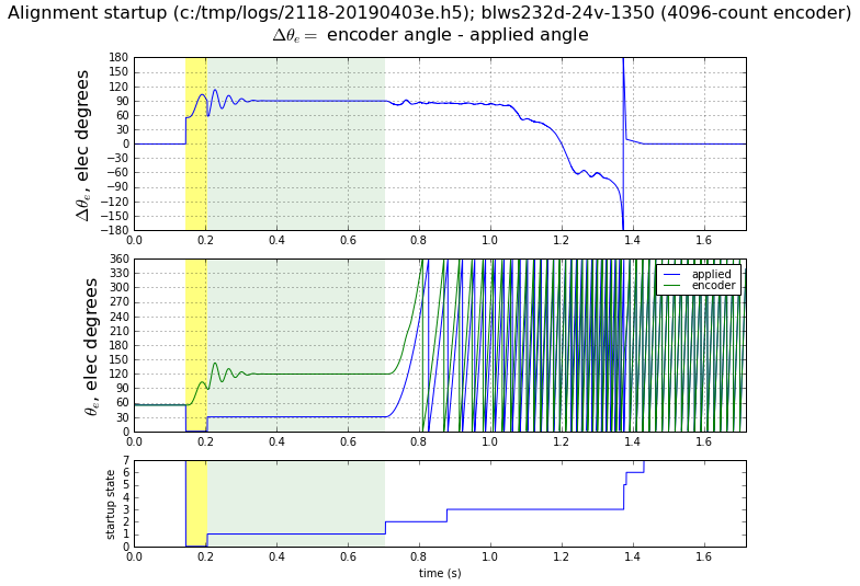
Figure 5.39 Align method with BLWS232D-24V-1350-1024SI5, \(\theta_0 = 0^\circ, \theta_1 = 30^\circ\)
The remaining graphs in this section show the use of the align method with the Anaheim Automation BLY342D-48V-3200-1024SI5. This motor has substantial cogging torque, and because of this, the success of the align method depends on initial conditions and the choice of startup angles. Figure 5.40 shows this motor during startup, with applied electrical angles of 0° during both rampup and align states: \(\theta_0 = \theta_1 = 0^\circ\). In this case, the initial angle of the motor \(\theta_{init}\) was around 65° from equilibrium, and the transient settles down quickly.
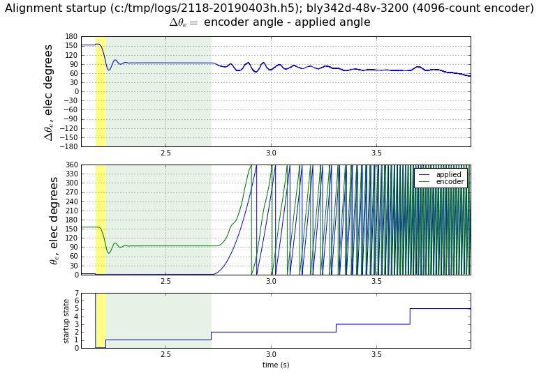
Figure 5.40 Align method with BLY342D-48V-3200-1024SI5, \(\theta_0 = \theta_1 = 0^\circ, \theta_{init}\approx 155^\circ\)
When the initial position of the rotor is roughly 180° from equilibrium, the rotor can get stuck in a detent at semistable equilibrium. Figure 5.41 shows such a case, where the rotor reaches the correct equilibrium eventually, but its transient is much longer.

Figure 5.41 Align method with BLY342D-48V-3200-1024SI5, \(\theta_0 = \theta_1 = 0^\circ, \theta_{init}\approx 275^\circ\)
Figure 5.42 shows almost the same starting angle, but this time it remains stuck in a semistable equilibrium. Note that during the align phase, highlighted green, the rotor angle does not move significantly, and remains approximately 270° ahead of the applied electrical angle, whereas in successful uses of the align method, it should reach equilibrium at 90° ahead of the applied electrical angle. In this case, the calculated commutation offset would be off by 180°, leading to backward instead of forward rotation.
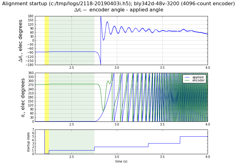
Figure 5.42 Align method with BLY342D-48V-3200-1024SI5, \(\theta_0 = \theta_1 = 0^\circ, \theta_{init}\approx 275^\circ\), This shows the case where the rotor is stuck in semistable equilibrium near its initial conditions.
The use of an angle shift can prevent this situation.
Figure 5.43 shows similar initial conditions but with the applied angle during the align phase shifted by 30°. Here the rampup phase remains stuck in semistable equilibrium, but the align phase is able to escape the detent and reach its intended position.
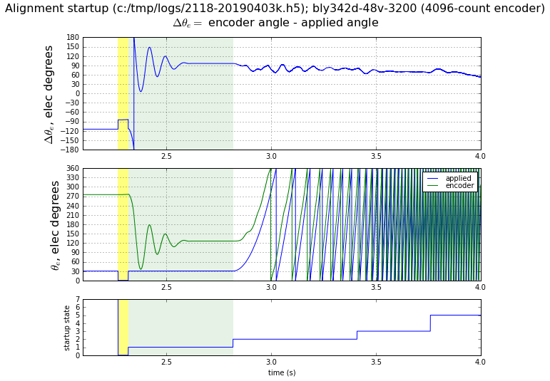
Figure 5.43 Align method with BLY342D-48V-3200-1024SI5, \(\theta_0 = 0^\circ, \theta_1 = 30^\circ, \theta_{init}\approx 275^\circ\).
Figure 5.43 shows similar initial conditions, with the applied angle during the align phase at 0° but at 330° during the rampup phase. In this case, the rampup phase provides enough torque to give the motor a kick and prevent it from getting stuck in equilibrium.
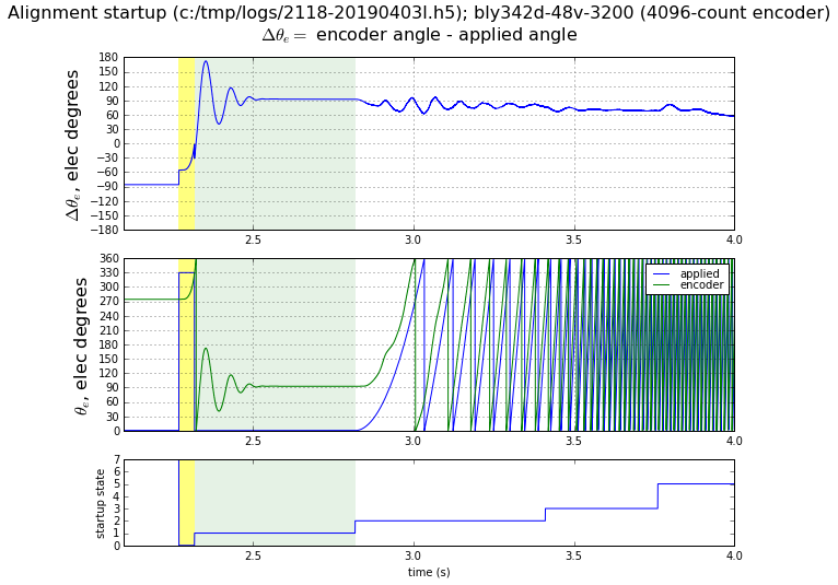
Figure 5.44 Align method with BLY342D-48V-3200-1024SI5, \(\theta_0 = 330^\circ, \theta_1 = 0^\circ, \theta_{init}\approx 275^\circ\).
This technique of adding an angle shift is not foolproof, but it does seem to be reasonably robust. Tests of several motors with high cogging torque were able to align successfully with an angle shift in the 30° - 60° range.
5.3.2.3.2.5. Accuracy and repeatability tests
The align method was tested with MCAF R4, and the resulting commutation offset from index
(motor.estimator.qei.position.commutationOffsetFromIndex) was compared against a reference
method using open-circuit voltage measurements of the motor terminals with the motor
rotated mechanically at constant speed.
Table 5.2 describes the results. In each case, 64 iterations of the align method were performed, with initial conditions at evenly-spaced angles spanning one electrical cycle. Except where noted, the settings for the align method are the default values of \(\theta_0 = 330^\circ\) during the rampup state and \(\theta_1 = 0^\circ\) during the align state (angle shift of 30°). Each motor was used with a dsPICDEM® MCLV‑2 Development Board, with default current limit of 2.29A, and default startup current at 91% of the current limit = 2.08A.
| mean \(\tilde\theta_{ofs}\) | max \(\tilde\theta_{ofs}\) | stdev \(\hat\theta_{ofs}\) | span \(\hat\theta_{ofs}\) | Test case |
|---|---|---|---|---|
| 0.39° | 0.43° | 0.07° | 0.18° | BLWS232D-24V-1350-1024SI5 |
| 1.00° | 1.50° | 0.28° | 0.97° | BLY171D-24V-4000 with 4096-line encoder |
| 15.44° | 189.35° | 54.47° | 352.62° | BLY342D-24V-3000-1024SI5, 30° angle shift |
| 3.68° | 4.43° | 0.44° | 2.46° | BLY342D-24V-3000-1024SI5, 60° angle shift |
| 3.44° | 3.91° | 0.42° | 1.41° | BLY342D-48V-3200-1024SI5 |
The error metrics are as follows:
- mean \(\tilde\theta_{ofs}\) — mean value of the commutation offset difference between the align method and the reference method
- max \(\tilde\theta_{ofs}\) — maximum value of the commutation offset difference between the align method and the reference method
- stdev \(\hat\theta_{ofs}\) — standard deviation of commutation offset estimated by the align method
- span \(\hat\theta_{ofs}\) — difference between minimum and maximum commutation offset estimated by the align method
The BLY342D-24V-3000-1024SI5 required a larger angle shift (60°) to work reliably. With the default value of 30°, initial conditions near 180° from equilibrium cause the motor to get stuck in semistable equilibrium. This is more severe with the BLY342D-24V-3000 than the BLY342D-48V-3200; both motors use the same lamination stack and rotor but are wound differently, with the BLY342D-24V-3000 having higher rated current and a lower value of \(K_e\), so that the 2.08A is not able to exert as much torque during the align phase.