Current measurement |
Current measurement |
Selects which method is used to measure motor phase currents |
Single channel |
Minimum time window |
Minimum time window required to measure current |
Single channel |
ADC trigger delay |
Delay between inverter switching state and ADC sampling point |
Estimators |
Primary estimator |
Selects which estimator is used for commutation and velocity feedback |
Estimators |
Active estimators |
Selects which estimators are active, in addition to
the primary estimator used for commutation |
Operating parameters |
Minimum velocity |
Determines minimum operating velocity |
Operating parameters |
Startup velocity |
Determines startup velocity |
Operating parameters |
Maximum velocity |
Determines maximum velocity command, as a ratio of nominal motor velocity |
Operating parameters |
Full-scale velocity |
Determines full-scale velocity, as a ratio of nominal motor velocity |
Operating parameters |
Outer loop controller |
Determines the variable controlled by the outer control loop |
Operating parameters |
Saliency: Saliency threshold |
Determines saliency ratio below which the motor’s saliency is neglected |
Operating parameters |
Slew rate: max acceleration |
Determines maximum velocity slew rate in motoring quadrants |
Operating parameters |
Slew rate: max deceleration |
Determines maximum velocity slew rate in generating quadrants |
Operating parameters |
Dynamic current limit type |
Determines which type (if any) of dynamic current limit algorithm to use |
Operating parameters |
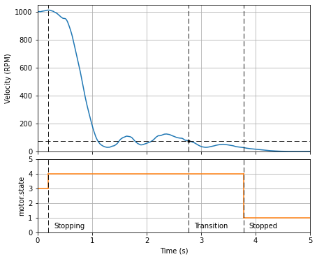
Closed-loop stopping |
Determines which type (if any) of closed-loop stopping to use |
Operating parameters |
Closed loop stopping: Speed |
speed at which the motor is considered stopped |
Operating parameters |
Closed loop stopping: Time |
time duration where the motor is below the stopping speed, after which the motor is considered stopped |
Operating parameters |
Coastdown: Velocity threshold |
Determines velocity threshold used to estimate when a motor stops |
Operating parameters |
Coastdown: Time |
Determines time to wait until a motor stops |
Flux control |
Flux control method |
Selects flux control method (or “None” if disabled) |
Flux control |
Current limit: Boundary type |
Selects method used for defining the commanded Idq boundary |
Flux control |
Current limit: Idmax |
Determines the maximum negative d-axis current |
Flux control |
Current limit: Iqmax |
Determines the maximum q-axis current |
Flux control |
Flux weakening: enable |
Determines if flux weakening is enabled |
Flux control |
Flux weakening: Voltage limit |
Determines the voltage amplitude limit used in flux weakening (FW) |
Flux control |
MTPA: Enable |
Determines if MTPA is enabled |
Flux control |
MTPA: Idmax-MTPA |
Displays the maximum d-axis current allocated to MTPA, as a function of \(L_d - L_q\) and \(I_{\max}\) (Indication only) |
Flux control |
MTPA: gain-MTPA |
Displays the maximum increase in torque due to MTPA (Indication only) |
Dead-time compensation |
Dead-time compensation method |
Selects dead-time compensation method (or “None” if disabled) |
Dead-time compensation |
Current linearity range |
Determines linear range of currents used for deadtime compensation; larger currents are treated as ±1 |
Dead-time compensation |
Forward gain |
Determines gain for dead-time compensation in the forward path |
Dead-time compensation |
Feedback gain |
Determines gain for dead-time compensation in the feedback path |
Fault detection |
Undervoltage margin |
Determines undervoltage threshold margin |
Fault detection |
Overvoltage margin |
Determines overvoltage threshold margin |
Fault detection |
Stall detect: enable |
Determines if stall detect is enabled |
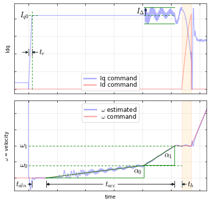
Startup |
Startup current |
Determines current used during startup |
Startup |
Rampup time |
Determines current rampup time during startup |
Startup |
Align time |
Determines time to remain in the align state during startup |
Startup |
Min accel time |
Determines minimum acceleration time during startup |
Startup |
Acceleration \(\alpha_1\) |
Determines fast acceleration rate |
Startup |
Acceleration \(\alpha_0\) |
Determines slow acceleration rate |
Startup |
Hold time |
Determines time to remain in the hold state during startup |
Startup |
Speed threshold \(\omega_0\) |
Determines speed threshold for switching to fast acceleration |
Startup |
Angle converge rate |
Determines rate of angle convergence during closed-loop transition of classic startup |
Startup |
Startup algorithm |
Selects startup method |
Startup |
Active damping: max amplitude |
Determines maximum amplitude of active damping current |
Startup |
Active damping: max gain |
Determines maximum gain of active damping |
Startup |
Active damping: speed threshold |
Determines the minimum velocity to enable active damping |
Overmodulation |
D-axis limit |
Determines the maximum d-axis voltage |
Overmodulation |
Q-axis limit |
Determines the maximum q-axis voltage |
Overmodulation |
Duty cycle feedback with clipping |
Determines when in the forward path duty cycle feedback is obtained |
AN1292 PLL |
Time constant |
Specifies the velocity estimation time constant |
AN1292 PLL |
Loop filter bandwidth |
Specifies the loop filter bandwidth |
AN1292 PLL |
Filter threshold |
Determines maximum velocity for slow filtering in the PLL |
Quadrature encoder |
Lines |
Specifies the number of lines of the encoder |
Quadrature encoder |
Index pulse present |
Specifies whether an index pulse is present |
Quadrature encoder |
Tracking loop time constant |
Determines bandwidth of tracking loop |
Quadrature encoder |
Synchronization method |
Selects method of synchronizing encoder with back-emf |
Quadrature encoder |
Align time |
Duration of alignment phase of startup |
Quadrature encoder |
Align angle shift |
Determines angle shift between rampup and align states of startup |
Quadrature encoder |
Align initial angle |
Determines initial angle used in rampup state of startup |
Quadrature encoder |
Align-and-sweep rate |
Determines rotation rate during align state of startup, when using align-and-sweep method |
Quadrature encoder |
Align-and-sweep setup angle |
Determines setup angle of align-and-sweep method, to allow transients to settle prior to measurements |
Quadrature encoder |
Pullout slip threshold |
Determines rotor slip threshold used for detecting a pullout condition |
Dynamic current limit |
Dynamic current limit |
Determines peak current |
Dynamic current limit |
Dynamic current limit |
Determines horizon current |
Dynamic current limit |
Dynamic current limit |
Determines relaxation time constant |
Dynamic current limit |
Dynamic current limit |
Determines decimation ratio |
Voltage control |
Low-pass filter time constant |
Determines q-axis low pass filter time constant |
Voltage control |
Proportional gain |
Determines voltage controller proportional gain |
Voltage control |
Time constant |
Determines voltage controller time constant |
Motion Control API |
Filter time constant Is |
Determines the time constant used for calculating low pass filtered value of amplitude of current in the motor (Is) |
Motion Control API |
Filter time constant Iq |
Determines the time constant used for calculating low pass filtered value of the measured q-axis current in the motor (Iq) |
Motion Control API |
ADC ISR user functions |
Determines if the ADC ISR user functions are called periodically in the MCAF ISR |
Board Service |
UI service period |
Determines the rate at which the board service ISR tasks get executed. |
Board Service |
Button debounce time |
Determines the length of time required to register a logical high signal as a button press. |
Board Service |
Long button press time |
Determines the amount of time before a button press is detected as a long button press. |
Optional analog inputs |
Temperature bridge |
Determines if the temperature bridge ADC input is sampled |
Optional analog inputs |
Temperature bridge: Overtemperature threshold |
Determines threshold for triggering an overtemperature fault |
Optional analog inputs |
Temperature bridge: Time constant |
Determines temperature low-pass filter time constant |
Optional analog inputs |
Temperature bridge: Slew rate |
Determines temperature slew rate |
Optional analog inputs |
Absolute voltage reference |
Determines if the absolute voltage reference ADC input is sampled |
Optional analog inputs |
Phase voltage: A |
Determines if the phase A ADC input is sampled |
Optional analog inputs |
Phase voltage: B |
Determines if the phase C ADC input is sampled |
Optional analog inputs |
Phase voltage: C |
Determines if the phase C ADC input is sampled |