3.7. State Machine
The motor control state machine can be described as a hierarchical state
machine, shown below in Figure 3.8.
The states are shown in blue; the names (MCSM_xxxx) are
the ones used in the application framework code. Transition conditions are shown
as labeled arrows.
This state machine is intended to treat the motor controller at a very high level: rather than concern itself with detailed information about the motor (is a stall occurring? is there an overvoltage?), the state machine is designed around general events like whether a fault has been detected, or whether a start or stop sequence is complete.
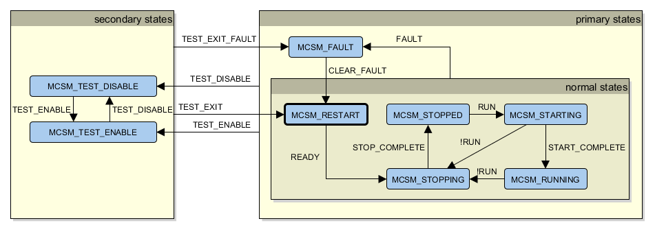
Figure 3.8 Motor controller state diagram
3.7.1. States
These states are divided into subgroups:
- Primary states: all the states except for those used in test operation.
- Normal states: states where a fault is not occurring.
MCSM_FAULT: a fault has occurred.
- Secondary states: all the states used in test operation. These states cause the normal state machine to be ignored, along with some of the fault detection algorithms that may produce false positives when in test modes.
The grouping here forms a hierarchical state machine. For example: any of the
normal states will transition to MCSM_FAULT if a fault has been detected.
(Traditional state machines would require transitions to MCSM_FAULT to be shown
from MCSM_STOPPED, MCSM_STARTING, MCSM_RUNNING, MCSM_STOPPING,
and MCSM_INIT.)
Further detail is given in the State Machine section.