5.1.7. Comparison between FOC and six-step control
There are several tradeoffs between FOC and six-step control of permanent magnet synchronous motors. As mentioned in the overview section, FOC adds several improvements in performance, with minor drawbacks, at the cost of some design and implementation complexity:
5.1.7.1. Torque capability
5.1.7.1.1. Torque degradation from angle error
Perfect FOC maintains the stator field perpendicular to the rotor flux. [1] An estimate of rotor angle is required (along with rotor flux, in the case of an induction motor). Torque in FOC is proportional \(I_q \cos\tilde{\theta}\), where \(\tilde{\theta}\) is the angle error from perfect perpendicularity.
In FOC, the \(\cos\tilde{\theta}\) term is generally very close to 1.
In six-step control, \(\tilde{\theta}\) cannot be guaranteed any better than 30°. This is because the current vector in six-step control is fixed at the center of each 60° sector, as shown in Figure 5.36 and Figure 5.37, and the angle error of at least one of the edges of each sector is 30° or more.

Figure 5.36 Six-step sectors
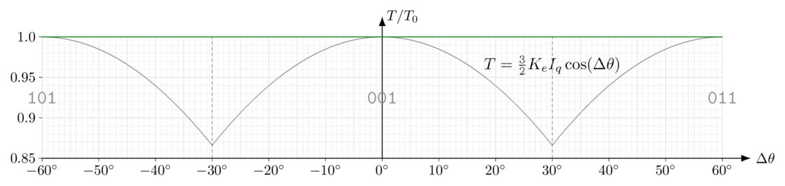
Figure 5.37 Torque vs. angle error in six-step control with perfect knowledge of sector edges
This torque dropoff near the edges of the six-step sector is significant. At high speeds, inertia smooths out high-frequency components of torque, and only the average of \(\cos\tilde{\theta}\) affects the system: with perfectly-aligned sectors, the average torque of six-step control is 95.5% of perfect FOC torque for the same current limit: six-step torque is about 4.5% lower.
At low speeds, this averaging is not present, and the best case for six-step control is that torque at the edges of sectors is 86.6% of FOC torque for the same current limit. Errors in angle sensing (misaligned Hall sensors, for instance) can lower this value further, and the torque falls off very quickly with higher angle error. When the load torque is high, this can cause the motor to become “stuck” at the edge of a sector, unable to overcome load torque.
FOC is also prone to angle error, but errors are not as significant. It would take about 17.3° angle error to reduce FOC torque by the same 4.5%. Figure 5.38 shows the impact of a 4° electrical error in the two cases:
FOC loses about 0.24% torque
Six-step loses about 0.24% torque (in addition to the 4.5% loss with perfect sector alignment) on average, but another few percent at one end of the sector.
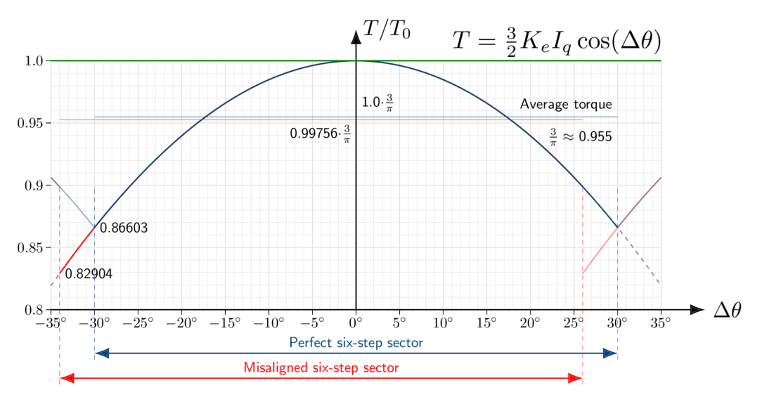
Figure 5.38 Torque vs. angle error in six-step control with imperfect knowledge of sector edges
Notes
5.1.7.1.2. Torque degradation from dynamics of commutation
As the commutation angle changes, FOC provides voltages that change continuously with electrical angle, and compensates automatically for the phase lag of stator inductance. (at steady state, a component of voltage is required to change current through the stator windings; see phasor analysis for more information)
Six-step commutation has the drawback that it must move the current vector in discrete jumps, by 60° at each transition between commutation sectors. At low speeds, this leads to a very short torque transient at each sector transition, usually accompanied by a faint “tick” sound.
At higher speeds, there are two major disadvantages of six-step commutation:
commutation instants occur more frequently (higher electrical frequency)
available voltage for commutation is reduced (back-emf uses up more of the voltage)
Commutation transients are no longer negligible; a significant fraction of each sector is spent making the current vector move. The total time during each sector is reduced, because the motor is operating at an increased electrical frequency. Peak current requirements increase slightly, to make up for lost torque at the beginning of each sector, which increases torque ripple. As back-emf requirements increase, the available voltage headroom is less, meaning that current transients take longer. At some point, it takes the entire commutation sector to work towards increasing current, and six-step control limits the available current.
Figure 5.39, Figure 5.40, Figure 5.41, and Figure 5.42 show this trend in a simulation of the Nidec Hurst DMA0204024B101 with increasing commutation frequency.
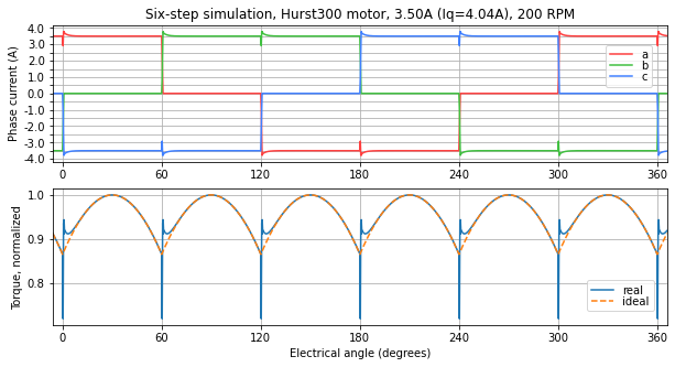
Figure 5.39 Simulation at 200 RPM — the commutation transient is very short
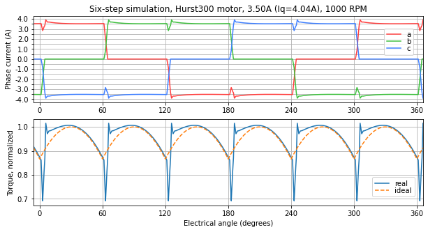
Figure 5.40 Simulation at 1000 RPM — the commutation transient is short but visible
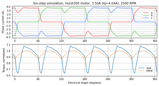
Figure 5.41 Simulation at 2500 RPM — the commutation transient takes more than one third of the total sector time, and steady-state current must be slightly higher to make up for the PI control transient
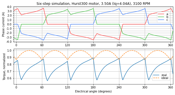
Figure 5.42 Simulation at 3100 RPM — due to voltage limits, the entire commutation sector is needed to increase motor current, and it never quite gets to the commanded current
Figure 5.43, Figure 5.44, and Figure 5.45 show measured current waveforms from a Nidec Hurst DMA0204024B101 operated in six-step from the dsPIC33CK Low Voltage Motor Control (LVMC) Development Board using code from Microchip’s AN957. This particular six-step motor controller does not use a current loop, and instead wraps a slower PI loop around estimated speed, so commutation transitions take longer than their counterparts in the simulations shown above. In these tests the mechanical load on the motor was approximately constant, so at higher speeds, the required current is higher to overcome six-step transient effects and deliver the same mechanical torque.
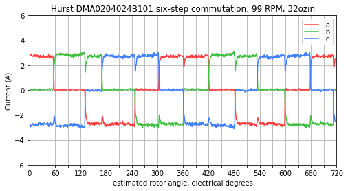
Figure 5.43 Measured currents at approximately 100 RPM — six-step currents are held fairly steady
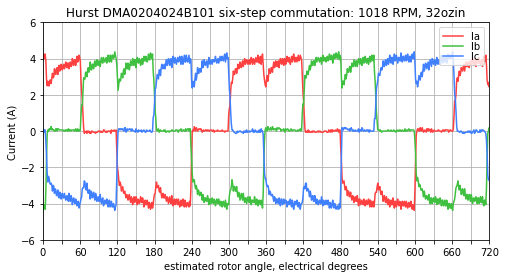
Figure 5.44 Measured currents at approximately 1000 RPM — a substantial fraction of the sector time is required to bring current to its steady-state value
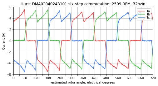
Figure 5.45 Measured currents at approximately 2500 RPM — commanded currents rise, and the control loop utilizes all the available voltage but cannot reach a steady-state value by the end of each sector.
FOC’s continuous commutation can achieve higher current at high speeds, making better use of available voltage, and minimizes torque ripple.
5.1.7.2. Torque ripple
At steady state in FOC (constant speed and load torque), as long as the current controller can maintain a constant current vector Idq, motor torque ripple is zero.
Six-step torque ripple is affected by two factors:
the \(\cos \theta\) torque dependency for constant current
commutation transients that make torque ripple worse at increasing speeds
5.1.7.3. Efficiency
The angle error of six-step causes excess I²R loss in the motor windings. Averaged over an electrical cycle — and neglecting the dynamics of commutation transients, which will increase the power dissipation further — for the same load torque, the I²R power dissipation in the windings is about 10% higher in six-step than in FOC:
\(\left(\frac{\pi}{3}\right)^2 \approx 1.0966\) under assumptions of constant current — if the motor speed or inertia is high enough or velocity control is slow enough that the commanded current does not change much within each commutation sector, then I²R loss in six-step is 9.7% higher than in FOC. Currents in this case are shown in Figure 5.46.
\(\frac{2\sqrt{3}}{\pi} \approx 1.1027\) under assumptions of constant torque — if the motor speed or inertia is low enough, or velocity control is fast enough, that the commanded current varies within each commutation sector to keep torque constant. (\(I \propto T/\cos\tilde\theta\) where angle error \(\tilde\theta\) varies from -30° to +30°) Currents in this case are shown in Figure 5.47.
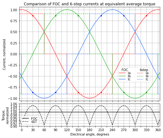
Figure 5.46 Comparison of FOC and six-step currents at equivalent average torque
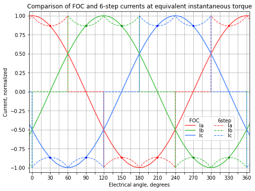
Figure 5.47 Comparison of FOC and six-step currents at equivalent instantaneous torque
Note: this does not mean that six-step is 10% less efficient; the exact decrease in efficiency depends on the motor construction and how much of the efficiency losses are resistive, meaning proportional to I². An oversized motor operating under some load condition in FOC where the mechanical power out is 98 W, and 2 W is dissipated in the windings, with negligible losses from other sources, would be 98% efficient; operating under the same conditions in six-step would raise winding dissipation by about 10% to 2.2W, making it 97.8% efficient.
5.1.7.4. Switching loss
Switching loss under PWM operation can be reduced in six-step compared to FOC, by reducing the number of actively-switching transistors.
Six-step requires either 1, 2, or 4 transistors to be actively switching, depending on the switching pattern used, as shown in Figure 5.48. One phase in each sector is unused, leaving two transistors completely off.
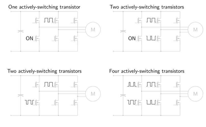
Figure 5.48 Six-step switching patterns, assuming phase C is open-circuited during one commutation sector.
1 or 2 actively-switching transistors: take the lowest-voltage motor terminal, turn on the lower transistor on that phase at 100% duty cycle. (See top row in Figure 5.48.)
1 transistor: take the highest-voltage motor terminal, and actively switch the upper transistor. (relying on the lower transistor’s diode to carry free-wheeling current)
2 transistors: actively switch both transistors of the highest-voltage motor terminal.
2 or 4 actively-switching transistors: choose complementary PWM duty cycles of the upper switches for the two active phases: for example, phase A at 15% duty cycle, phase B at 85% duty cycle. Two transistors are enough if relying on diodes to carry free-wheeling current. (See bottom row in Figure 5.48.)
The corresponding situations for FOC are either 2, 3, 4, or 6 actively-switching transistors, as shown in Figure 5.49. (Two transistors can be kept out of active switching by choosing the lowest-voltage motor phase and turning on its low-side transistor; the number of actively-switching transistors remaining depends on whether synchronous rectification is used in a given half-bridge.)
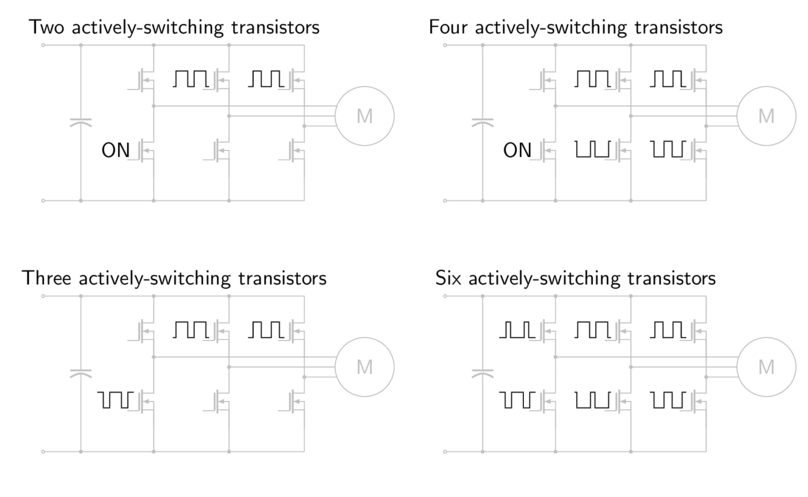
Figure 5.49 FOC switching patterns
There are trade-offs in that reducing the number of actively-switching transistors usually increases the ripple current in the motor at the switching frequency, or will cause more conduction loss in the power stage diodes.
In low-voltage motor drives where MOSFETs are used in the power stage, switching loss is usually small compared to conduction loss, and there’s no reason to try to reduce switching losses.
In motor drives that utilize IGBTs for higher voltage operation (powered by AC mains or electric vehicle batteries), switching loss is greater, whereas conduction loss in diodes is a much smaller concern.
Optimization of switching loss is a system-level task: motor control engineers should be discussing with their circuit designer counterparts to find the best solution.
5.1.7.5. Current management
Aside from commutation transients from one sector to the next, six-step can be summarized by a single current:
the highest-voltage motor terminal H has current I flowing into the motor terminal
the lowest-voltage motor terminal L has the same current I flowing out of the motor terminal
the remaining motor terminal M is open-circuited, conducting zero current
FOC requires knowledge of the current vector, which has two degrees of freedom (three phase currents, but they add to zero, so knowing any two can determine the third)
5.1.7.5.1. Current sensing
Because six-step control requires sensing one current, a single DC current sensor can be used.
FOC requires either one, two, or three current sensors, depending on the method:
three current sensors provides the highest accuracy and least noise
two current sensors provides knowledge about all three currents, with more noise and worse gain/offset accuracy than three current sensors, but otherwise no loss of information
a single DC current sensor can be used (Single-channel current measurement) with some constraints on signal conditioning and PWM duty cycle, and an increase in complexity, by sampling the current at multiple instants within the PWM period
Systems with severe cost constraints may require the use of a single DC current sensor. (Note: please see section on cost optimization)
5.1.7.5.2. Current range
For the same instantaneous torque, six-step and FOC require the same range of currents. (See Figure 5.47.)
If equivalent instantaneous torque is not required, but we want to know how the current ranges compare for the same average torque, then the situation changes. (See Figure 5.46.) For the same average torque, equivalent current amplitudes can be written for six-step and FOC. In six-step, current I6 flows into one terminal of the motor and out another. If the FOC current is Iq in amplitude, then:
FOC requires about 10.3% higher peak current sense range than six-step, for the same motor. This is true even though six-step is less efficient: current I6 into one terminal and out another has the equivalent three-phase vector magnitude of current that is \(\frac{2}{\sqrt{3}}I_6 \approx 1.1547 I_6\), so that six-step current sensing sneaks by with a lower peak current requirement.
With FOC, the worst-case commutation angle with current amplitude Iq is where Iq flows into (or out of) one motor terminal, and half of this current flows out of (or into) each of the other two terminals. The best-case commutation angle for this current amplitude is where \(\frac{\sqrt{3}}{2}I_q\) flows into one motor terminal and out of another, and the third terminal carries zero current. Current sensors have to cover the full range of ±Iq, however.
See Figure 5.46 for a graphical portrayal; at the 30/90/150/210/270/330 degree points, the FOC current amplitudes are lower by 4.5% (a factor of \(3/\pi\)) than the six-step current for equivalent average torque, but the FOC waveforms require higher current ranges at the peaks of the sine waves.
In practical terms, this means that current sense circuitry, overcurrent circuitry, and (to a lesser extent) gate drives need to be designed to cover the full instantaneous phase current, so the requirements are slightly lower for six-step — if average torque rather than instantaneous torque is the determining factor.
System components with ratings that depend more on root-mean-square current due to thermal reasons, such as connectors, wires, the power stage, and the motor itself, require higher ratings for six-step than for FOC. (See Efficiency)
5.1.7.6. Cost optimization
Cost optimization is a system-level task. Increased performance in current sensing can increase the utilization of the motor and power stage, and actually reduce the overall system cost.
For example, imagine a digitally-controlled system that contains a $50 motor and $5 of power electronics, capable of carrying 10A continuous current, and $2 current-sensing components that are accurate within ±2%, which require derating the motor to use only 9.6A of its capability in the worst-case. (Digital control limited to 9.8A in firmware, so that if the sensors are underestimating current by 2%, it ensures the real motor current is no more than 10A — but if the sensors overestimate current by 2%, then only 9.6A might be used.)
If better current-sensing components are used, that cost $2.50 but are accurate within ±0.5%, a slightly smaller motor capable of carrying 9.7A continuous current could be used to ensure that worst-case capability is at least 9.6A. (Digital control limited to 9.65A in firmware, corresponding to between 9.6A and 9.7A of real-world current.) If this 3% reduction in maximum current and torque saves more than $0.50 in the cost of the motor and power stage, then it is worth choosing more expensive current-sensing components.
Techniques that “save money” because they allow less expensive current sensing (higher tolerance, reduced number of sensors) under nominal operation may actually cost more, because the overall system design sees lower worst-case utilization of motor and power electronics that will need to be oversized as a result.
5.1.7.7. Control complexity
Six-step controllers can be simpler than FOC, requiring only these components:
sector determination
a scalar current loop, or no current control loop
sector application (determining how to apply the current loop output to different PWM phases)
FOC requires a vector current loop and coordinate transforms — these are roughly 2 – 3 times the computational equivalent of the components listed above for six-step. The lower CPU usage for six-step can allow the system designer to work with a higher PWM switching frequency and electrical frequency for certain types of motors. (Higher switching frequency reduces current ripple in low-inductance motors; electrical frequency is proportional to motor velocity, so higher electrical frequency is required for high-speed motors.)
In addition, if a sensorless position/velocity estimator is required, the complexity is higher for FOC than for sensorless six-step estimators.