5.6. Current limit
5.6.1. Overview
The outer loop controller (velocity control, for example) commands q-axis current which saturates at well-defined limits. These limits are configurable, and may have a fixed or dynamic behavior. Dynamic current limits are appropriate when short peak transient currents are desired.
5.6.2. Implications of operating at the current limit
When the outer loop controller saturates at the current limit, it can no longer achieve its control goal, and will instead come as close to that goal as it can without exceeding the current limit.
The MCAF velocity controller, for example, will no longer regulate velocity if the current limit is reached, and will instead command the current limit while in control saturation. If the velocity command is 3000 RPM, but at a 10 A current limit the motor can only reach 2400 RPM instead, then the velocity controller will maintain 10 A at 2400 RPM.
In field-oriented control, constant q-axis current results in nearly constant torque over a wide range — so, in practice, the motor speed will be determined by the balance between motor torque and load torque. Speed can change fairly quickly if load torque changes and exceeds the current limit.
In motoring operation, speed will reach stable equilibrium when motor and load torque balance. Increases in load torque will slow the motor down, and decreases load torque allow the motor to speed up until the outer loop comes out of saturation.
In regenerating operation, the equilibrium is unstable: if the current limit is reached, and there is still an external mechanical torque driving the motor shaft, then the motor will speed up until the external mechanical torque decreases. For near-constant-torque loads (for example, a load of ore attached to a conveyor belt or winch that is being lowered in a controlled fashion), reaching the torque limit can cause a runaway condition where the speed increases rapidly until something breaks.
For this reason, it is important to consider the entire system and understand the desired behavior of motor and load, in order to select a current limit.
5.6.3. Dynamic current limit
Continuous current limits in both the motor and power electronics are determined by thermal constraints: specifically, the rated temperatures of the motor windings and transistor junctions. At the continuous current limit, motor and transistors can operate indefinitely. But the thermal time constants of motors and transistors are usually longer than transient torque requirements: this means that both motor and transistors have the capability of carrying currents above the continuous limit for a short time.
A useful dynamic current limit algorithm meets several requirements:
At any given time, the current limit \(I_{\lim}\) varies between continuous and peak limits:
\(I_{\mathrm{cont}} \le I_{\lim} \le I_{\mathrm{peak}}\)The magnitude of the commanded motor current vector \(I_{dq,\mathrm{cmd}}\) should always be kept below the current limit; in other words, \(I_{d,\mathrm{cmd}}{}^2 + I_{q,\mathrm{cmd}}{}^2 \le I_{\lim}{}^2\)
The dynamics of the current limit should be controlled so that motor and transistors are kept within their safe operating temperature.
MCAF R7 provides such a current limit algorithm.
5.6.4. Thermal modeling background
A detailed description of thermal modeling and the selection of current limit parameters is beyond the scope of this documentation at present, but there are a few key principles to note.
For stator windings, the thermal time constant is often tens of seconds or even minutes, and transient currents of 3-5× larger than the continuous limit are common in some applications.
In transistors, there are three relevant materials: the transistor junction, the transistor case, and the heat sink.
The junction is small and thin, and heats up quickly (typically on the order of milliseconds or tens of milliseconds), but the thermal resistance between junction and case is typically small; in many cases, the junction may be only a few degrees hotter than the case.
The transistor case, especially in larger packages such as TO-252 (DPAK), TO-263 (D²PAK), TO-220, and TO-247, contains a metal tab with enough thermal capacity to act as a short temporary heat sink.
External heat sink — if present, this provides additional thermal capacity and a path for heat to flow to ambient. (Note: on a printed circuit board, copper pours with thermal vias are an effective method of providing at least some additional thermal capacity and conductivity from the PCB itself. See AN8826 PCB Mounting Guidelines for Surface Mount Packages for more information.)
Figure 5.89 shows a thermal simulation of a MOSFET dissipating constant power loss after time \(t=0\). The junction-to-case temperature rises to its final value very quickly. Transistor case and heatsink heat up more slowly. The thermal capacity of transistor case and heatsink allow peak transient currents above the continuous current capacity.
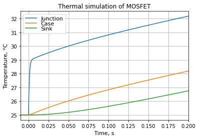
Figure 5.89 Thermal simulation of a MOSFET dissipating 10W, RθJC = 0.4 K/W.
5.6.5. Available current limit algorithms in MCAF
The following are available current limit algorithms in MCAF:
Static current limit (No dynamic current limit) — maintains a constant continuous current limit, taking the lower value of the board continuous current limit and the motor continuous current limit
Simple current limit (“dyn1”) — uses a first-order model dependent on motor current.
5.6.6. Peak and continuous limits
Continuous and peak current limits are independent of the algorithm used.
The continuous current should be chosen based on a system-level requirement, for example, continuous operation for 15 minutes with motor and drive in free air of up to 50°C ambient. (In some cases, “continuous” really is an indefinitely long period of time, and in others the time is limited.)
Peak current should be chosen as the minimum of all short-time constraints, typically including the following:
motor: demagnetization current — above some point, stator magnetic field can cause irreversible demagnetization of rotor magnets.
motor: iron saturation — above some point, torque degrades and inductance decreases, causing an increase in ripple current. Iron saturation usually occurs at a lower current than the demagnetization current.
drive: ADC input current saturation — can’t control what you aren’t able to measure
drive: hardware current limit — this should be reserved for detecting catastrophic failures, for example a short-circuit within one of the transistors, or an external short-circuit of one of the motor phases to either the positive or negative DC link
drive: gate drive — above a certain current, the gate drive may not work reliably. Put another way: the gate drive should be designed and tested to handle some peak current that should never be exceeded.
5.6.7. Implementation notes
So far, all versions of MCAF (R1 – R7) support only symmetric current limits: the same current level is applied to both positive and negative currents, whether the motor is rotating forward or backward, and whether the motor is in motoring or regenerative operation.
The simple dynamic current limit has been added in MCAF R7.
For other implementation notes, see the detailed information in each current limit option.