PolarFire Video Kit Setup Instructions
Table of Contents
Introduction
These instructions describe how to setup, compile and run an example on the PolarFireVideo Kit with the MiV_RV32 Reference Design. The instructions are for Linux but similar steps can be followed on Windows using Cygwin.
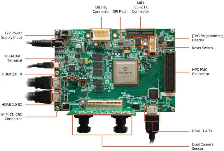
Step 1: Board Connections
The following cables must be connected to the board for use with SmartHLS:
- Power cable (connects to
12V Power Supply Input). - Mini-USB cable for serial communication to the board and embedded JTAG programmer. The same cable is used for both. Alternatively, you use the External FP6 programmer.
- Jumper
J28must be open to use the external programmer, or closed to use the embedded programmer.
Step 3: Install Host PC Applications
The following programs are required to be installed on the host PC to set up the PolarFire Video Kit:
- SmartHLS v2023.2 or newer.
- Libero v2023.2 or newer.
- SoftConsole v2021.3 or later.
- A serial communication terminal of your choosing. in this guide we will use tio.
Step 4: Write, compile and run a simple test program
During the test we will open the 3 terminals labeled below:
UART Terminal: We will use this to see the stdout from the program.SmartHLS terminal: We will use this to run SmartHLS commands from the command line.OpenOCD terminal: We will use this to launch OpenOCD manually.
Create a temporary directory, for example, test, and use your favorite text editor to
write the following 4 files under this directory:
$> mkdir test
$> cd test
Create a simple_add.c file with the following content:
#include <stdio.h>
#include <stdint.h>

uint32_t hw_add(uint32_t a, uint32_t b) {
   #pragma HLS function top
   #pragma HLS interface default type(axi_target)
   return a + b;
}

int main() {
   uint32_t sum;
   uint32_t a = 2, b = 3;
   sum = hw_add(a, b);

   int error = (sum != a + b);
   printf("\n%s\n", error ? "FAIL" : "PASS");
   return error;
}
Create the Makefile with the following content:
NAME=simple_add
SRCS=$(NAME).c
LOCAL_CONFIG = -legup-config=config.tcl
LEVEL = $(SHLS_ROOT_DIR)/examples
include $(LEVEL)/Makefile.common
Create a config.tcl file:
source $env(SHLS_ROOT_DIR)/examples/legup.tcl
set_project PolarFire MPF300 MiV_SoC
Create a gdb.txt file with the following instructions for gdb to connect to
OpenOCD, load the .elf binary into the MiV_RV32’s memory and run the code:
set $target_riscv = 1
set mem inaccessible-by-default off
set arch riscv:rv32
target extended-remote localhost:3333
load
run
Note that we used the SHLS_ROOT_DIR environment variable, it should point to where
SmartHLS is installed. On the SmartHLS Terminal type the following:
$> export SHLS_ROOT_DIR=/path/to/Microchip/SmartHLS_2023.2/SmartHLS
Now run the SmartHLS SoC flow to:
- Compile the
hw_addfunction into a Verilog module- Integrate the module into the MiV_RV32 Reference Design. See MiV_RV32 Reference Design
- Run RTL synthesis
- Run place and route
- Check timing
- Program the FPGA
The command below will invoke all these tasks as they are dependencies to program the FPGA. This will take a few minutes:
$> shls -a soc_accel_proj_program
Now cross-compile the simple_add.c program. This will generate a
hls_output/simple_add.elf file.
$> shls soc_sw_compile_accel
In the UART terminal open the UART connection. Your device may be different:
$> tio /dev/ttyUSB0 -b 115200
In the OpenOCD terminal launch OpenOCD.
$> openocd -f board/microsemi-riscv.cfg
Now go back to the SmartHLS terminal and run gdb to execute the code on the MiV_RV32.
$> riscv64-unknown-elf-gdb ./hls_output/simple_add.elf -x ./gdb.txt
At this point you should see the word PASS in the UART terminal. You can
type Ctrl+C and then press q to terminate the gdb session.
Also, you can press Ctrl+C on the OpenOCD terminal to close the program,
otherwise it would not release the JTAG cable.