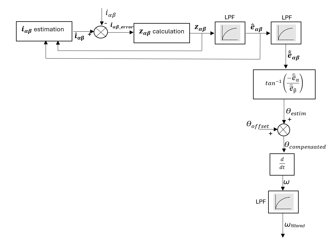
The Sliding Mode Observer (SMO) is used here for the velocity and rotor
angle estimation of a PMSM to achieve sensorless control. The algorithm
uses the PMSM current dynamics and forces the estimated current to match the
measured current using a sliding mode gain. The estimated back-emf is used to calculate
the position and velocity as shown in the implementation block diagram. The implementation is based on
AN1078, with some improvements in parameter calculations.
5.4.6.2. Implementation Block Diagram and Description
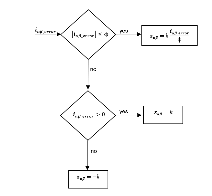
To prevent possible chattering, a smoothly-saturating function has been used instead of a signum function.
The sliding gains (\(k\)) and the boundary layer width (\(\Phi\)) have been calculated using Lyapunov and describing function methods.
The low-pass filters (LPFs) used for the back-emf filtering are adaptive filters, such that the cut-off frequency is always equal to the reference speed.
These filters introduce a delay which needs to be compensated (\(\theta_{offset}\)). The estimated position from the back-emf is differentiated with respect to time to estimate the speed.
This estimated speed is further filtered using another adaptive LPF to get the final speed.