Constraints Manual
SmartHLS accepts user-provided constraints that impact the automatically generated
hardware. These constraints can be specified using the SmartHLS IDE and are
stored in the Tcl configuration file config.tcl in your project directory.
This reference section explains the constraints available for SmartHLS.
The main constraints available from the SmartHLS IDE are:
- Set target clock period: CLOCK_PERIOD
- Print the HDL output to a single output file: SINGLE_HDL_OUTPUT_FILE
- Set custom config file: set_custom_config_file
- Set test bench file: set_custom_test_bench_file
- Set test bench module: set_custom_test_bench_module
- Set operation latency: set_operation_latency
- Set FPGA family and device: set_project
- Set resource constraint: set_resource_constraint
- Set FPGA synthesis top-level module: set_synthesis_top_module
- Set FPGA synthesis top-level file: set_synthesis_top_module_file
A few debugging constraints are available from the SmartHLS IDE:
- Stalling input/output FIFOs in CoSimulation: COSIM_<INPUT|OUTPUT>_FIFO_STALL_PROB
- Keep signals with no fanout: KEEP_SIGNALS_WITH_NO_FANOUT
- Insert simulation assertions (for debugging): VSIM_ASSERT
Commonly Used Constraints
CLOCK_PERIOD
This is a widely used constraint that allows the user to set the target clock period for a design. The clock period is specified in nanoseconds.
It has a significant impact on scheduling: the scheduler will schedule operators into clock cycles using delay estimates for each operator, such that the specified clock period is honored. In other words, operators will be chained together combinationally to the extent allowed by the value of the CLOCK_PERIOD parameter.
SmartHLS has a default CLOCK_PERIOD value for each device family that is supported (see table in SmartHLS Constraints).
Category
HLS Constraints
Value Type
Integer represent a value in nanoseconds
Valid Values
Integer
Default Value
Depends on the target device
Dependencies
None
Applicable Flows
All devices and flows
Test Status
Actively in-use
Examples
set_parameter CLOCK_PERIOD 15
SINGLE_HDL_OUTPUT_FILE
When set to 1, this TCL parameter constrains SmartHLS-generated Verilog RTL and VHDL wrapper modules to a single Verilog file (<Project Name>.v) and a single VHDL file (<Project Name>.vhd) respectively. By default, each Verilog top-level module (and its child modules) is printed to a separate output file (<Project Name>_<Top-Level Name>.v), and each VHDL wrapper module of a top-level is printed to a separate VHDL file (<Project Name>_<Top-Level Name>.vhd).
Category
HLS Constraints
Value Type
Boolean
Valid Values
0, 1
Default Value
SINGLE_HDL_OUTPUT_FILE 0
Dependencies
None
Applicable Flows
All devices and flows
Test Status
Actively in-use
Examples
set_parameter SINGLE_HDL_OUTPUT_FILE 1
set_custom_config_file
If you want to add advanced SmartHLS Tcl constraints that are not listed in the SmartHLS IDE constraints dialog you need to use a custom config file. Be careful not to modify the config.tcl constraints file directly, since config.tcl will be overwritten whenever you make changes in the SmartHLS IDE constraints dialog.
To add a custom config file, open the SmartHLS Constraints Menu. Select Set custom config file from the dropdown and enter the Constraint Value as “custom_config.tcl”. Then click Add:

Now click OK:

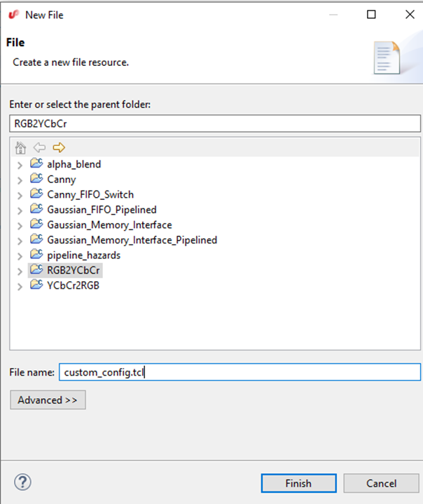
Now in the Project Explorer, right click and select New->File:

Enter the name of “custom_config.tcl”. This should match the file name entered in the Set HLS Constraints previously. Click Finish:
set_custom_test_bench_file
This TCL command is to specify the user-provided custom testbench file
that defines the custom testbench module, which is set via set_custom_test_bench_module.
This is not needed for SW/HW co-simulation.
Category
Simulation
Value Type
String
Dependencies
set_custom_test_bench_module "user_tb"
Applicable Flows
All devices and flows
Test Status
Actively in-use
Examples
set_custom_test_bench_file user_tb.v
set_custom_test_bench_module
This TCL command is to specify the name of the user-provided testbench module to be using for RTL simulation. The testbench file must also be specified with set_custom_test_bench_file.
Category
Simulation
Value Type
String
Dependencies
set_custom_test_bench_file user_tb.v
Applicable Flows
All devices and flows
Test Status
Actively in-use
Examples
set_custom_test_bench_module "user_tb"
set_operation_latency
This Tcl command sets the latency of a given operation. Latency refers to the number of clock cycles required to complete the computation; an operation with latency one requires one cycle, while zero-latency operations are completely combinational, meaning multiple such operations can be chained together in a single clock cycle. This command is used to schedule each type operation to take the specified number of cycles.
This Tcl command should only be used by advanced SmartHLS users.
Category
HLS Constraints
Value Type
set_operation_latency <operation> <constraint> <operation> is a string <constraint> is an integer
Valid Values
See Default and Examples Note: operator name should match the operation database file: boards/PolarFire/PolarFire.tcl or boards/set_operation_latency.tcl
See ENABLE_AUTOMATIC_MEMORY_LATENCY_SETTING on default latency for memory latency. See ENABLE_AUTOMATIC_MULTIPLY_MODE_SETTING on default latency for multiplies.
Default Values
fp_add 14
fp_subtract 14
fp_multiply 11
fp_divide_32 33
fp_divide_64 61
fp_truncate_64 3
fp_extend_32 2
fp_fptosi 6
fp_sitofp 6
signed_comp_o 1
signed_comp_u 1
reg 2
Location Where Default is Specified
examples/legup.tcl
Dependencies
None
Applicable Flows
All devices and flows
Test Status
Actively in-use
Examples
# set memory operations to take 3 cycles
set_operation_latency memory_port 3
Note
When implementing an integer multiply operation, SmartHLS’s default behaviour is to optimize for timing (Fmax) by mapping a multiply operation to target DSPs. When a multiply operation is wider than the DSP can support, SmartHLS splits the multiply into multiple DSPs and automatically inserts registers to help RTL synthesis tool to utilize registers in DSPs better, and hence achieve better timing.
However, this split-multiply feature does not support a user-configurable
latency.
When set_operation_latency multiply X is specified by user, SmartHLS will
turn off the split-multiply feature and use a generic multiplier that will
adapt to user-specified latency.
SmartHLS will also print a warnign as follows,
Warning: Detected set_operation_latency setting for integer multiplier. However, configurable latency is incompatible with the multiply splitting feature. Disabling multiply splitting feature and the normal multiplier modules will be used.
Similarly, set_resource_constraint multiply X will trigger the same
behaviour because the split-multiply does not support sharing the
multipliers.
set_project
This parameter sets the default target project, or device, used. Changing the project also updates the associated family and board parameters.
This parameter has 3 arguments:
- FPGA Family (e.g. PolarFire®).
- FPGA Device: This can either be the board name (e.g. MPF300), or the device number (e.g. MPF300TS-1FCG1152I).
- Flow:
hw_onlyorIcicle_SoC.Icicle_SoCis only available when targeting the PolarFire® SoC Icicle kit device.
Category
Board and Device Specification
Value Type
String
Valid Values
See Examples
Default Value
PolarFire MPF300 hw_only
Location Where Default is Specified
examples/legup.tcl
Dependencies
None
Applicable Flows
All devices and flows
Test Status
Actively in-use
Examples
set_project PolarFire MPF300 hw_only
set_project PolarFire MPF300T-1FCG1152I hw_only
set_project SmartFusion2 FUTUREM2SF hw_only
set_project SmartFusion2 M2S025T-FG484I hw_only
set_project IGLOO2 M2GL005-1FG484 hw_only
set_resource_constraint
This Tcl command constrains the resource allocated by SmartHLS.
For instance, to only have a single divider in the entire circuit, user can specify: set_resource_constraint divide 1.
This makes SmartHLS instantiate a maximum of 1 divider in the circuit, and if there are multiple division operations required, they will share the same divider.
- Note: A constraint on “divide” will apply to:
- signed_divide_8
- signed_divide_16
- signed_divide_32
- signed_divide_64
- unsigned_divide_8
- unsigned_divide_16
- unsigned_divide_32
- unsigned_divide_64
It can also be used to constrain the number of memory ports. To make all memories single-ported: set_resource_constraint memory_port 1
For memory ports, only 1 and 2 are valid values, as FPGA RAMs have up to 2 ports.
This Tcl command should only be used by advanced SmartHLS users.
Category
HLS Constraints
Value Type
set_resource_constraint <operation> <constraint> <operation> is a string <constraint> is an integer
Valid Values
See Default and Examples Note: operator name should match the device family operation database file: boards/PolarFire/PolarFire.tcl
Default Values
memory_port 2
divide 1
modulus 1
multiply 2
fp_add 1
fp_subtract 1
fp_multiply 1
fp_divide 1
fp 1
Location Where Default is Specified
examples/legup.tcl
Dependencies
None
Applicable Flows
All devices and flows
Test Status
Actively in-use
Examples
set_resource_constraint signed_divide_16 3
set_resource_constraint signed_divide 2
set_resource_constraint divide 1
Note
When implementing an integer multiply operation, SmartHLS’s default behaviour is to optimize for timing (Fmax) by mapping a multiply operation to target DSPs. When a multiply operation is wider than the DSP can support, SmartHLS splits the multiply into multiple DSPs and automatically inserts registers to help RTL synthesis tool to utilize registers in DSPs better, and hence achieve better timing.
However, this split-multiply feature cannot support sharing multipliers.
When set_resource_constraint multiply X is specified by user, SmartHLS will
turn off the split-multiply feature and use a generic multiplier that can be
shared by more than one multiply operations.
SmartHLS will also print a warning as follows,
Warning: Detected set_resource_constraint setting for integer multiplier. However, multiplier sharing is incompatible with the multiply splitting feature. Disabling multiply splitting feature and the normal multiplier modules will be used.
Similarly, set_operation_latency multiply X will trigger the same
behaviour because the split-multiply does not support user-configured
multiply latency.
set_synthesis_top_module
This TCL command specifies the name of the Verilog module that will be set as the top-level module when creating a Libero project for synthesis, place and route. By default, the top-level function (see Specifying the Top-level Function) is set as the top-level module for the Libero project, however user may want to provide wrapper HDL module that instantiates the SmartHLS-generate top-level module. In this case, this Tcl command can be used to give the name of the wrapper module.
Category
Libero
Value Type
String
Dependencies
None
Applicable Flows
All devices and flows
Test Status
Actively in-use
Examples
set_synthesis_top_module "wrapper_top"
set_synthesis_top_module_file
When set_synthesis_top_module is used to set a different wrapper module as
the top-level for synthesis, place & route, use this command to specify the
file that defines the wrapper module.
Category
Libero
Value Type
String
Dependencies
set_synthesis_top_module "wrapper_top"
Applicable Flows
All devices and flows
Test Status
Actively in-use
Examples
set_synthesis_top_module_file custom_synthesis_top.v
Debugging Constraints
COSIM_<INPUT|OUTPUT>_FIFO_STALL_PROB
The COSIM_INPUT_FIFO_STALL_PROB and COSIM_OUTPUT_FIFO_STALL_PROB
parameters can be used to exercise halting data injecting to input FIFO or
backpressuring the output FIFO during SW/HW Co-Simulation.
When the parameter is set to a value between 1 and 99, representing the
probablity to halt input FIFO or backpressure output FIFO, the
SmartHLS-generated CoSimulation testbench will randomly halt the data
injectiion to input FIFO or backpressure output FIFO, which will then cause the
SmartHLS-generated circuit to stall during simulation.
Category
HLS Constraint
Value Type
Integer
Valid Values
0-99
Default Value
0: disabled
Location Where Default is Specified
examples/legup.tcl
Dependencies
None
Applicable Flows
All devices and flows
Test Status
Actively in-use
Examples
set_parameter COSIM_INPUT_FIFO_STALL_PROB 50
set_parameter COSIM_OUTPUT_FIFO_STALL_PROB 40
KEEP_SIGNALS_WITH_NO_FANOUT
If this parameter is enabled, all signals will be printed to the output Verilog file, even if they don’t drive any outputs.
Category
HLS Constraint
Value Type
Integer
Valid Values
0, 1
Default Value
1
Location Where Default is Specified
examples/legup.tcl
Dependencies
None
Applicable Flows
All devices and flows
Test Status
Actively in-use
Examples
set_parameter KEEP_SIGNALS_WITH_NO_FANOUT 1
VSIM_ASSERT
When set to 1, this constraint causes assertions to be inserted in the Verilog produced by SmartHLS. This is useful for debugging the circuit to see where invalid values (X’s) are being assigned.
Category
Simulation
Value Type
Integer
Valid Values
0, 1
Default Value
0
Location Where Default is Specified
examples/legup.tcl
Dependencies
None
Applicable Flows
All devices and flows
Test Status
Actively in-use
Examples
set_parameter VSIM_ASSERT 1
Advanced Constraints
These are not available from the SmartHLS GUI.
IFCONV_PREDICATE_LOADS
This constraint sets whether load instructions should be predicated during if-conversion. By default, it is set to 1 to predicate load instructions to avoid resource contention between mutually exclusive loads. If there is no resource contention between mutually exclusive loads, it can set to 0 avoid inserting predication logic.
Category
HLS Constraints
Value Type
Boolean
Valid Values
0, 1
Default Value
1
Location Where Default is Specified
examples/legup.tcl
Dependencies
None
Applicable Flows
All devices and flows
Test Status
Actively in-use
Examples
set_parameter IFCONV_PREDICATE_LOADS 1
LATENCY_REDUCTION
The LATENCY_REDUCTION settings control the SmartHLS’ expression balancing optimization, of which the objective is to reduce the circuit latency. Below are the related settings,
| Parameter Name | Default Value | |
|---|---|---|
| LATENCY_REDUCTION | 1 | The main switch that enables or disables expression balancing. Setting to 0 disables all expression balancing optimizations. |
| LATENCY_REDUCTION_ALLOW_FP_REORDERING | 0 | By default expression balancing does not re-order floating-point operations to prevent loss of precisions.
Setting to 1 allows to re-order floating-point operations if the circuit latency can be reduced.
|
| LATENCY_REDUCTION_REDUCE_FP_CONVERSIONS | 0 | Setting to 1 will allow SmartHLS to cancel out back-and-forth conversion between floating-point and integer, with potential variations in numerical values.
For example, the following conversions can be cancelled when this setting is 1.
int a = (int)(float)(3); // a == 3.float b = (float)(int)(1.2); // b == 1.2 instead of 1. |
| LATENCY_REDUCTION_BALANCE_MULTI_USE_NODE | 0 | By default expression balancing does not optimize the intermediate operations that have multiple uses, to avoid potential increase of resource usage.
Setting to 1 allows to re-order intermediate operations that have multiple uses and more latency reduction could be achieved.
|
Category
HLS Constraints
Value Type
Integer
Valid Values
0, 1
Default Value
As listed in the table above.
Location Where Default is Specified
examples/legup.tcl
Dependencies
None
Applicable Flows
All devices and flows
Test Status
Actively in-use
Examples
set_parameter LATENCY_REDUCTION 1
set_parameter LATENCY_REDUCTION_ALLOW_FP_REORDERING 0
set_parameter LATENCY_REDUCTION_REDUCE_FP_CONVERSIONS 0
set_parameter LATENCY_REDUCTION_BALANCE_MULTI_USE_NODE 0
ENABLE_AUTOMATIC_MEMORY_LATENCY_SETTING
Enable determining memory latency for reads automatically according to the target clock period and timing model of the board. Memory latency is set to 2 when the target clock period is less than the delay of memory for the target device, otherwise is set to 1. Increasing the memory latency can result in higher circuit Fmax at the expense of higher circuit latency. The auto-determined latency can be found in Memory Usage section of SmartHLS report.
Setting the operation latency for a RAM will override the latency automatically calculated. See set_operation_latency for a list of valid memory port latency. The threshold for switching are listed in the table below.
| Device | Use Memory Latency of 2 when Target Period is less than (ns) |
|---|---|
| PolarFire, PolarFireSoC | 4.167 |
| IGLOO2, SmartFusion2 | 4.167 |
ENABLE_AUTOMATIC_MEMORY_LATENCY_SETTING controls the latency for the following memory constraints. Each constraint can be used with set_operation_latency <Name> <latency> to override the auto-determined latency.
| Name | Description |
|---|---|
local_memory_port |
Controls the memory latency of Local Memory used by a single function. |
shared_local_memory_port |
Controls the memory latency of Shared-Local Memory shared by multiple functions. |
axi_slave_ram_memory_port |
Controls the memory latency of Legacy AXI4 Slave Interface |
memory_port |
Controls the memory latency of Memory Controller |
SmartHLS does not automatically determine the latency for external_memory_port as it is only for creating an interface with the RAMs outside of the circuit. However, for SmartHLS SoC Flow, external_memory_port controls the latency for the on-chip memory buffers.
Category
HLS Constraints
Value Type
Boolean
Valid Values
0, 1
Default Value
1
Location Where Default is Specified
examples/legup.tcl
Dependencies
None
Applicable Flows
All devices and flows
Test Status
Actively in-use
Examples
set_parameter ENABLE_AUTOMATIC_MEMORY_LATENCY_SETTING 1
ENABLE_AUTOMATIC_MULTIPLY_MODE_SETTING
Enable determining multiply mode automatically according to the target clock period and timing model of the board. Fully pipelined mode (i.e., using both input and output registers of each Math block) will be used when the target clock period is less than the delay of a Math block, otherwise half pipelined mode (i.e., using only the input register of each Math block) will be used.
Fully pipelined mode can result in higher circuit Fmax at the expense of higher circuit latency. This functionality is disabled when set_resource_constraint multiply X or set_operation_latency multiply X is defined. The threshold for switching are listed in the table below.
| Device | Fully Pipelined Mode when Target Period is less than (ns) |
|---|---|
| PolarFire, PolarFireSoC | 3.704 |
| IGLOO2, SmartFusion2 | 4.169 |
Below is a table of latency for multiplications of unsigned integers for selected bit widths for reference:
| (Bit Width) x (Bit Width) = (Bit Width) | Half Pipelined Mode Latency | Full Pipelined Mode Latency |
|---|---|---|
| 8 x 8 = 8 | 1 | 2 |
| 8 x 8 = 16 | 1 | 2 |
| 16 x 16 = 16 | 1 | 2 |
| 16 x 16 = 32 | 1 | 2 |
| 32 x 32 = 32 | 2 | 4 |
| 32 x 32 = 64 | 3 | 5 |
| 64 x 64 = 64 | 6 | 11 |
| 64 x 64 = 128 | 9 | 17 |
Category
HLS Constraints
Value Type
Boolean
Valid Values
0, 1
Default Value
1
Location Where Default is Specified
examples/legup.tcl
Dependencies
None
Applicable Flows
All devices and flows
Test Status
Actively in-use
Examples
set_parameter ENABLE_AUTOMATIC_MULTIPLY_MODE_SETTING 1
MULTIPLY_SPLITTING_FULLY_PIPELINED
Multipliers are implemented in Math (DSP) blocks. When this constraint is set to 0, only the input register of each Math block is used, whereas when it is set to 1, both the input and output registers of each Math block are used. Utilizing just the input register will result in lower latency but utilizing both input and output registers will result in higher Fmax. When ENABLE_AUTOMATIC_MULTIPLY_MODE_SETTING is set to 1, which is the default, SmartHLS will automatically decide which multiplier mode should be used based on the target clock period constraint.
Category
HLS Constraints
Value Type
Boolean
Valid Values
0, 1
Default Value
0
Location Where Default is Specified
examples/legup.tcl
Dependencies
None
Applicable Flows
All devices and flows
Test Status
Actively in-use
Examples
set_parameter MULTIPLY_SPLITTING_FULLY_PIPELINED 1
SOC_AXI_INITIATOR
This is an SoC integration parameter to allow integrating HLS-generated modules into a custom user-defined SmartDesign system. The parameter specifies the AXI initiator interface used by the processor in the user-defined SmartDesign system to connect to the HLS module’s AXI target interface. This AXI initiator interface is used by the processor to control and transfer data to/from the HLS modules.
Please refer to SoC integration parameters for more details on using this Tcl parameter.
Category
HLS Constraints
Value Type
String
Default Value (Based on Icicle SoC reference design)
AXI2AXI_TO_HLS:AXI4_MASTER
Dependencies
None
Applicable Flows
SoC Flow Only
Test Status
Actively in-use
Examples
set_parameter SOC_AXI_INITIATOR AXI2AXI_TO_HLS:AXI4_MASTER
SOC_AXI_TARGET
This is an SoC integration parameter to allow integrating HLS-generated modules into a custom user-defined SmartDesign system. The parameter specifies the AXI target interface in the user-defined SmartDesign system where the HLS module’s AXI initiator interface can connect to. This AXI target interface is used by the HLS modules to access shared memory (DDR) directly.
Please refer to SoC integration parameters for more details on using this Tcl parameter.
Category
HLS Constraints
Value Type
String
Default Value (Based on Icicle SoC reference design)
AXI2AXI_FROM_HLS:AXI4_SLAVE
Dependencies
None
Applicable Flows
SoC Flow Only
Test Status
Actively in-use
Examples
set_parameter SOC_AXI_TARGET AXI2AXI_FROM_HLS:AXI4_SLAVE
SOC_BD_NAME
This is an SoC integration parameter to allow integrating HLS-generated modules into a custom user-defined SmartDesign system. The parameter specifies the name of the SmartDesign system to integrate the HLS modules into.
Please refer to SoC integration parameters for more details on how to use this Tcl parameter.
Category
HLS Constraints
Value Type
String
Default Value (Based on Icicle SoC reference design)
FIC_0_PERIPHERALS
Dependencies
None
Applicable Flows
SoC Flow Only
Test Status
Actively in-use
Examples
set_parameter SOC_BD_NAME FIC_0_PERIPHERALS
SOC_CLOCK
This is an SoC integration parameter to allow integrating HLS-generated modules into a custom user-defined SmartDesign system. The parameter specifies the name of the clock to connect to the HLS modules. Currently, all HLS modules use the same clock.
Please refer to SoC integration parameters for more details on how to use this Tcl parameter.
Category
HLS Constraints
Value Type
String
Default Value (Based on Icicle SoC reference design)
ACLK
Dependencies
None
Applicable Flows
SoC Flow Only
Test Status
Actively in-use
Examples
set_parameter SOC_CLOCK ACLK
SOC_CPU_MEM_BASE_ADDRESS
This is an SoC integration parameter to allow integrating HLS-generated modules into a custom user-defined SmartDesign system. The parameter specifies the base address of the memory window in the shared memory space (DDR) that can be accessed by the HLS module’s AXI initiator interfaces. This address is used to configure the AXI interconnect that HLS modules connect to for accessing the shared memory.
Note that the value for the parameter is specified in hexadecimal format and must be prefixed with 0x.
Please refer to SoC integration parameters for more details on how to use this Tcl parameter.
Category
HLS Constraints
Value Type
Hexadecimal
Default Value (Based on Icicle SoC reference design)
0x80000000
Dependencies
None
Applicable Flows
SoC Flow Only
Test Status
Actively in-use
Examples
set_parameter SOC_CPU_MEM_BASE_ADDRESS 0x80000000
SOC_CPU_MEM_SIZE
This is an SoC integration parameter to allow integrating HLS-generated modules into a custom user-defined SmartDesign system. The parameter specifies the size of the shared memory (DDR) space that the HLS module’s AXI initiator interfaces can access.
Note that the value for the parameter is specified in hexadecimal format and must be prefixed with 0x.
Please refer to SoC integration parameters for more details on how to use this Tcl parameter.
Category
HLS Constraints
Value Type
Hexadecimal
Default Value (Based on Icicle SoC reference design)
0x60000000
Dependencies
None
Applicable Flows
SoC Flow Only
Test Status
Actively in-use
Examples
set_parameter SOC_CPU_MEM_SIZE 0x60000000
SOC_DMA_ENGINE
This is an SoC integration parameter to allow integrating HLS-generated modules into a custom user-defined SmartDesign system. The parameter specifies the type of DMA engine to use in the system for transferring data to/from HLS modules.
| DMA Engine | Description |
|---|---|
| HARD_DMA | Uses the DMA available in the PolarFire SoC MSS. This implies that the CPUs to be used are the RISC-V U54 application cores in the MSS.
|
| SOFT_DMA | Automatically instantiates a DMA engine on the FPGA fabric and be connected to the SmartHLS AXI interconnect along with the SmartHLS IP modules.
Currently this option is not enabled, but will be in a future release.
|
Please refer to SoC integration parameters for more details on how to use this Tcl parameter.
Category
HLS Constraints
Value Type
String
Default Value (Based on Icicle SoC reference design)
HARD_DMA
Dependencies
None
Applicable Flows
SoC Flow Only
Test Status
HARD_DMA is actively in-use; SOFT_DMA will be made available in a future release
Examples
set_parameter SOC_DMA_ENGINE HARD_DMA
SOC_FABRIC_BASE_ADDRESS
This is an SoC integration parameter to allow integrating HLS-generated modules into a custom user-defined SmartDesign system. The parameter specifies the base address of the CPU memory space that is reserved for all HLS modules. The control registers and on-chip memory buffers of HLS modules are allocated and mapped within this memory window. This address is also used to configure the AXI interconnect that HLS modules connect to.
Note that the value for the parameter is specified in hexadecimal format and must be prefixed with 0x.
Please refer to SoC integration parameters for more details on how to use this Tcl parameter.
Category
HLS Constraints
Value Type
Hexadecimal
Default Value (Based on Icicle SoC reference design)
0x70000000
Dependencies
None
Applicable Flows
SoC Flow Only
Test Status
Actively in-use
Examples
set_parameter SOC_FABRIC_BASE_ADDRESS 0x70000000
SOC_FABRIC_SIZE
This is an SoC integration parameter to allow integrating HLS-generated modules into a custom user-defined SmartDesign system. The parameter specifies the size of the CPU memory space that is reserved for all HLS modules. The control registers and on-chip memory buffers of HLS modules are allocated and mapped within this memory window. This address is also used to configure the AXI interconnect that HLS modules connect to.
Note that the value for the parameter is specified in hexadecimal format and must be prefixed with 0x.
By default, 4MB of size is reserved. If this is larger than what HLS modules require, it can just be left for future use. Reserving a larger window does not mean more on-chip memory will be used.
Please refer to SoC integration parameters for more details on how to use this Tcl parameter.
Category
HLS Constraints
Value Type
Hexadecimal
Default Value (Based on Icicle SoC reference design)
0x400000
Dependencies
None
Applicable Flows
SoC Flow Only
Test Status
Actively in-use
Examples
set_parameter SOC_FABRIC_SIZE 0x400000
SOC_POLL_DELAY
This parameter controls how often an accelerator driver function polls the status register of an HLS module to check for its completion. By default, the delay is set to 0, which means the processor will continuously poll the status. However, it may be beneficial to insert a delay in polling to reduce CPU usage and power consumption. The poll delay is specified in microseconds.
Please refer to SoC integration parameters for more details on how to use this Tcl parameter.
Category
HLS Constraints
Value Type
Integer; represents a value in microseconds
Valid Values
Integer
Default Value (Based on Icicle SoC reference design)
0
Dependencies
None
Applicable Flows
SoC Flow Only
Test Status
Actively in-use
Examples
set_parameter SOC_POLL_DELAY 10
SOC_PROFILER_COUNTER
This parameter specifies whether or not to include a hardware counter to help profile SoC-based designs. The counter is not included by default.
For more information, see SoC Profiler.
Category
HLS Constraints
Value Type
Boolean
Valid Values
0, 1
Default Value
0
Dependencies
None
Applicable Flows
SoC Flow Only
Test Status
Actively in-use
Examples
set_parameter SOC_PROFILER_COUNTER 1
SOC_RESET
This is an SoC integration parameter to allow integrating HLS-generated modules into a custom user-defined SmartDesign system. The parameter specifies the name of the reset signal to connect to the HLS modules. Currently, all HLS modules use the same reset. Note that the reset polarity must be active high.
Please refer to SoC integration parameters for more details on how to use this Tcl parameter.
Category
HLS Constraints
Value Type
String
Default Value (Based on Icicle SoC reference design)
ARESETN
Dependencies
None
Applicable Flows
SoC Flow Only
Test Status
Actively in-use
Examples
set_parameter SOC_RESET ARESETN
STRENGTH_REDUCTION
Strength reduction is an optimization that converts multiply-by-constant into shifts and additions:
Info: StrengthReduction: Replacing multiply by constant (i26 33038) with 3 adders:
        - (1 << 1) + (1 << 4) + (1 << 8) + (1 << 15)
Info: StrengthReduction: Replacing multiply by constant (i26 6416) with 3 adders:
        + (1 << 4) + (1 << 8) + (1 << 11) + (1 << 12)
Info: StrengthReduction: Replacing multiply by constant (i26 28784) with 3 adders:
        - (1 << 4) + (1 << 7) - (1 << 12) + (1 << 15)
Info: StrengthReduction: Replacing multiply by constant (i26 4680) with 3 adders:
        + (1 << 3) + (1 << 6) + (1 << 9) + (1 << 12)
Info: StrengthReduction: Replacing multiply by constant (i26 33024) with 1 adder:
        + (1 << 8) + (1 << 15)
This optimization saves DSP blocks on the FPGA but can also increase LUT usage in the design.
You can tune the number of adders allowed per multiplier with the constraint: STRENGTH_REDUCTION_ADDERS_ALLOWED_PER_MULTIPLIER
Category
HLS Constraints
Value Type
Integer
Valid Values
0, 1
Default Value
1
Location Where Default is Specified
examples/legup.tcl
Dependencies
None
Applicable Flows
All devices and flows
Test Status
Actively in-use
Examples
set_parameter STRENGTH_REDUCTION 1
STRENGTH_REDUCTION_ADDERS_ALLOWED_PER_MULTIPLIER
Strength reduction is an optimization that converts multiply-by-constant into shifts and additions:
Info: StrengthReduction: Replacing multiply by constant (i26 33038) with 3 adders:
        - (1 << 1) + (1 << 4) + (1 << 8) + (1 << 15)
The STRENGTH_REDUCTION_ADDERS_ALLOWED_PER_MULTIPLIER constraint allows you to tune the number of adders allowed per multiplier (default is 3). Strength reduction for multiply-by-constants will not be performed if this requires more adders than allowed:
i26 16828 is composed of 4 adders:
- (1 << 2) + (1 << 6) + (1 << 7) + (1 << 8) + (1 << 14)
Skipping conversion otherwise would need too many additions.
In this example, we would need 4 adders which is more than the default of 3, meaning strength reduction will not occur and SmartHLS will keep the multiplier.
Category
HLS Constraints
Value Type
Integer
Valid Values
Positive Integer
Default Value
3
Location Where Default is Specified
examples/legup.tcl
Dependencies
STRENGTH_REDUCTION must be on
Applicable Flows
All devices and flows
Test Status
Actively in-use
Examples
set_parameter STRENGTH_REDUCTION_ADDERS_ALLOWED_PER_MULTIPLIER 3
SYNTHESIS_CLOCK_PERIOD
This constraint allows the user to override the SDC clock period constraint for synthesis, P&R, and timing analysis.
By default, when this constraint is not specified, the same CLOCK_PERIOD constraint for HLS is used for the SDC clock period constraint. However, it may be useful to give a tighter SDC clock period constraint to close timing.
The clock period is specified in nanoseconds.
Category
HLS Constraints
Value Type
Integer; represents a value in nanoseconds
Valid Values
Integer
Default Value
N/A
Dependencies
None
Applicable Flows
All devices and flows
Test Status
Actively in-use
Examples
set_parameter SYNTHESIS_CLOCK_PERIOD 10
USE_FIFO_FOR_PIPELINE_REG
In a pipeline circuit where multiple stages of the circuit are concurrently active and processing different loop iterations (or function calls), pipeline registers are used to retain and propagate a variable value from the value-producing stage to the value-use stage. The pipeline registers are essentially a chain of shift registers with additional control logic. When the chain of pipeline registers is long, it may be more resource-efficient to implement the pipeline registers as a block-RAM FIFO rather than shift registers.
When this parameter is enabled, Smart HLS will examine each chain of pipeline registers and use the implementation (FIFO or shift register) that is estimated to be more resource-efficient.
Category
HLS Constraint
Value Type
Integer
Valid Values
0, 1
Default Value
1
Location Where Default is Specified
examples/legup.tcl
Dependencies
None
Applicable Flows
All devices and flows
Test Status
Actively in-use
Examples
set_parameter USE_FIFO_FOR_PIPELINE_REG 1
COSIM_FREE_RUNNING_DATAFLOW_TOP
The COSIM_FREE_RUNNING_DATAFLOW_TOP parameter can be useful for dataflow
designs which contain conditionally-executed tasks. When the top-level module
uses dataflow, this parameter will make the top-level module free-running, i.e.,
its start signal will be tied to 1. This parameter should not be enabled if an
AXI Target interface is used.
Category
HLS Constraint
Value Type
Boolean
Valid Values
0, 1
Default Value
0: disabled
Location Where Default is Specified
examples/legup.tcl
Dependencies
None
Applicable Flows
All devices and flows
Test Status
Alpha release
Examples
set_parameter COSIM_FREE_RUNNING_DATAFLOW_TOP 1